Community project
M5Stack Camera App
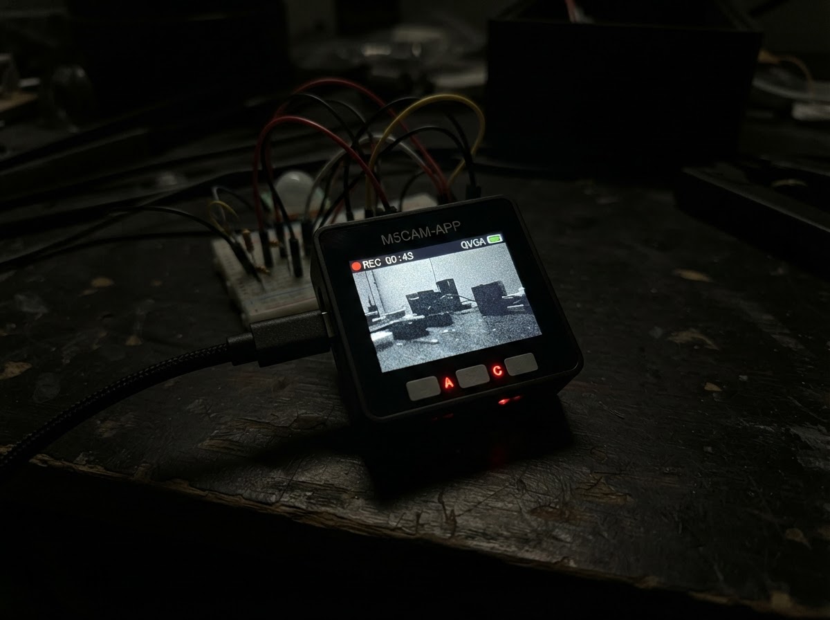
This project turns an M5Stack Tab5 into a camera control interface with a large touchscreen display. The built-in ESP32 microcontroller runs firmware that renders a capture button and status messages on the 1280×720 screen, ready for future camera integration.
Following this guide, makers will receive a complete parts list, wiring diagram, and step-by-step assembly instructions. The firmware is provided and can be uploaded directly to the Tab5. Once assembled and powered via USB, the device displays an interactive capture interface that serves as a foundation for adding live camera preview and image capture capabilities.
Wiring diagram
Assemble it in 4 steps
1. Leave the built-in parts in place
Use the Tab5 as it came from the factory. Its screen, touch panel, and camera are already connected inside the case, so this version has no loose parts or jumper wires to add.
- Keep the protective film on the screen only if it does not make touch taps unreliable.
- Do not open the Tab5 case to reach the camera connector; forcing internal connectors can damage the board.
2. Check the display label
Look at the product sticker or label on your Tab5 before first use. This app uses the current Tab5 display support that covers the listed screen variants, but the label is useful if a future screen problem needs diagnosing.
- Place the Tab5 on a non-conductive desk so its screen is not scratched.
- Do not swap or remove the battery while the Tab5 has power; disconnecting it without a clean shutdown can corrupt its settings.
3. Power the Tab5 by USB
Connect a USB cable to the Tab5's USB port. The cable supplies power and lets Schematik send the app to the board.
- Use a data-capable USB cable; some charging-only cables cannot transfer the app.
- Do not use a damaged cable or power adapter, because unreliable power can make the screen restart.
4. Try the capture control
After deploying, tap the large CAPTURE button near the bottom of the screen. The button briefly changes color and explains that live camera capture is waiting for future support.
- Tap the center of the button with a fingertip rather than a sharp object.
- This version does not save a photo or show a camera image; it is an honest interface shell, not a working camera capture feature.
Deploy the firmware
#include <Arduino.h>
#include <M5Unified.h>

namespace {
constexpr int SCREEN_WIDTH = 1280;
constexpr int SCREEN_HEIGHT = 720;
constexpr int BUTTON_X = 440;
constexpr int BUTTON_Y = 540;
constexpr int BUTTON_W = 400;
constexpr int BUTTON_H = 100;

bool captureMessageVisible = false;
uint32_t captureMessageStartedAt = 0;

bool pointInCaptureButton(int32_t x, int32_t y) {
  return x >= BUTTON_X && x < (BUTTON_X + BUTTON_W) &&
         y >= BUTTON_Y && y < (BUTTON_Y + BUTTON_H);
}

void drawCaptureButton(bool pressed) {
  const uint32_t fill = pressed ? 0x9C1B : 0x001F;
  M5.Display.fillRoundRect(BUTTON_X, BUTTON_Y, BUTTON_W, BUTTON_H, 18, fill);
  M5.Display.drawRoundRect(BUTTON_X, BUTTON_Y, BUTTON_W, BUTTON_H, 18, 0xFFFF);
  M5.Display.setTextDatum(middle_center);
  M5.Display.setTextColor(0xFFFF, fill);
  M5.Display.setTextSize(3);
  M5.Display.drawString("CAPTURE", SCREEN_WIDTH / 2, BUTTON_Y + BUTTON_H / 2);
}

void drawStatusArea() {
  M5.Display.fillRect(80, 420, SCREEN_WIDTH - 160, 72, 0x0000);
  M5.Display.setTextDatum(middle_center);
  M5.Display.setTextSize(2);
  if (captureMessageVisible) {
    M5.Display.setTextColor(0xFFE0, 0x0000);
    M5.Display.drawString("Capture is ready. Live camera support is not available yet.",
                          SCREEN_WIDTH / 2, 455);
  } else {
    M5.Display.setTextColor(0xBDF7, 0x0000);
    M5.Display.drawString("Preview will appear here when camera support is added.",
                          SCREEN_WIDTH / 2, 455);
  }
}

void drawScreen() {
  M5.Display.fillScreen(0x0000);
  M5.Display.fillRoundRect(80, 70, SCREEN_WIDTH - 160, 300, 24, 0x2104);
  M5.Display.drawRoundRect(80, 70, SCREEN_WIDTH - 160, 300, 24, 0x7BEF);

  M5.Display.setTextDatum(middle_center);
  M5.Display.setTextColor(0xFFFF, 0x2104);
  M5.Display.setTextSize(4);
  M5.Display.drawString("CAMERA PREVIEW", SCREEN_WIDTH / 2, 175);
  M5.Display.setTextColor(0xBDF7, 0x2104);
  M5.Display.setTextSize(2);
  M5.Display.drawString("The built-in camera is not enabled in this version.",
                        SCREEN_WIDTH / 2, 255);

  drawStatusArea();
  drawCaptureButton(false);
}

void showCaptureNotice() {
  drawCaptureButton(true);
  delay(120);
  drawCaptureButton(false);
  captureMessageVisible = true;
  captureMessageStartedAt = millis();
  drawStatusArea();
}
}  // namespace

void setup() {
  auto config = M5.config();
  M5.begin(config);
  M5.Display.setRotation(1);
  drawScreen();
}

void loop() {
  M5.update();

  const auto touch = M5.Touch.getDetail();
  if (touch.wasClicked() && pointInCaptureButton(touch.x, touch.y)) {
    showCaptureNotice();
  }

  if (captureMessageVisible && millis() - captureMessageStartedAt >= 3000) {
    captureMessageVisible = false;
    drawStatusArea();
  }
}
Remix this project
Make it yours in one click
Open a full copy of this project in your own Schematik workspace — diagram, code, parts, and assembly steps included. Swap the sensor, add features, or redesign the whole thing with AI. The author's original stays untouched.