Community project
Magnetic Tape Delivery Robot
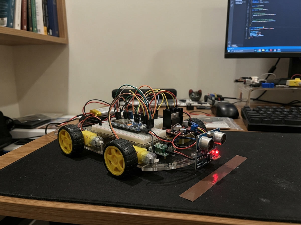
This guide builds a four-wheel delivery robot that follows magnetic tape lines on the floor using dual ESP32 boards and ultrasonic obstacle detection. The robot combines a sensor node for line tracking with a motor controller that manages speed, direction, and safety—making it suitable for autonomous material transport in warehouses, labs, or maker spaces.
You'll assemble a complete mobile platform with four DC gear motors, dual HC-SR04 ultrasonic sensors, a reed switch for magnetic stop points, and status LEDs. The guide includes a wiring diagram, full parts list, firmware code for both ESP32 boards, and step-by-step assembly instructions to get your robot tracking and delivering safely.
Wiring diagram

Gather all the parts
Assemble it in 7 steps
1. Set up the battery power safely
With the battery disconnected, connect battery_2s BAT+ to the master switch and fuse, then from the switched positive lead to buck_logic VIN+. Connect battery_2s BAT- to buck_logic VIN- and make this the shared ground rail. Set buck_logic VOUT+ to exactly 5.0 V with a multimeter before plugging in either ESP32; VOUT- is the shared ground. Connect the switched battery positive lead directly to both L298N VS terminals for motor power.
- Use red wire for switched battery positive and black wire for every ground wire.
- Keep the battery unplugged while moving wires on the breadboard.
- Do not connect the 2S battery directly to an ESP32 3V3 pin — that can damage the board.
- The L298N motor supply must not be taken through an ESP32 board because motor current can burn the board traces.
2. Build the magnetic sensor bar
Mount hall_a3144, hall_44e, and hall_ky024 in one straight 16-position row below the front of the chassis, with every sensing face the same small distance above the magnetic tape. Power the A3144 and 44E switches from 5 V and ground, and connect each open-collector OUT lead through its own 10 kΩ pull-up resistor to 3V3 before it reaches ESP32-A. Power each KY-024 module from 3V3 and ground, then connect only its DO pin to ESP32-A. Use ESP32-A GPIOs 4, 5, 13, 16, 17, 18, 19, 34 for sensors S1–S8 and GPIOs 21, 22, 23, 25, 26, 27, 32, 33 for S9–S16.
- Test each sensor with the actual floor tape before fixing it permanently.
- Keep motor wires away from this bar and twist each sensor signal wire with a ground wire where possible.
- Do not power a KY-024 module from 5 V when its DO pin goes to an ESP32 — its 5 V output can damage the ESP32 input.
- Do not omit the pull-up resistors on bare A3144 or 44E switches; without them the signal will float and give random readings.
3. Join the two ESP32 boards
Connect ESP32-A GPIO27 to ESP32-B GPIO14 as the one-way sensor-data wire, and connect ESP32-A GND to ESP32-B GND as the shared ground. Feed both ESP32 boards from the regulated 5 V output at their 5V/VIN pins. Do not use GPIO1 or GPIO3 for this link because those pins are used by the USB programming connection.
- Use a two-wire JST connector for the data wire and ground so the sensor bar controller can be unplugged.
- A 3.3 V ESP32 signal can connect directly to the other ESP32 input.
- The two boards must share ground or the UART data signal will be unreliable.
4. Wire the left and right motor sides
Remove the ENA and ENB jumper caps from both L298N boards. On l298n_left, connect IN1 to GPIO4, IN2 to GPIO5, and ENA to GPIO13; join IN3 to IN1, IN4 to IN2, and ENB to ENA so the left-front and left-rear motors always move together. Connect OUT1/OUT2 to motor_fl and OUT3/OUT4 to motor_rl. On l298n_right, connect IN1 to GPIO18, IN2 to GPIO19, and ENA to GPIO21; join IN3 to IN1, IN4 to IN2, and ENB to ENA. Connect OUT1/OUT2 to motor_fr and OUT3/OUT4 to motor_rr.
- Lift the chassis so all four wheels are off the floor for the first motor test.
- If one wheel turns backward, swap that motor's two wires at its L298N output.
- Keep fingers, loose wires, and clothing clear of the wheels during powered tests.
- L298N boards can become hot; stop testing if a driver is too hot to touch briefly.
5. Add obstacle and stop wiring
Wire each HC-SR04 VCC to 5 V and GND to ground. Connect the front TRIG pin to GPIO26 and rear TRIG pin to GPIO27. For each ECHO wire, connect the sensor ECHO to a 10 kΩ resistor, join the far end to the ESP32 input, then connect a 20 kΩ resistor from that same joined point to ground: front goes to GPIO16 and rear goes to GPIO17. Wire reed PIN2 to ground and PIN1 to GPIO22; place resistor_reed_pullup between PIN1 and 3V3.
- The two resistors on each ECHO wire reduce its 5 V signal to a safe 3.3 V signal.
- Mount the front ultrasonic sensor facing forward and the rear one facing backward.
- Never connect an HC-SR04 ECHO pin straight to an ESP32 GPIO — its 5 V signal can damage the ESP32.
6. Connect the status lights
Connect GPIO2 through resistor_led_red to led_red ANODE, GPIO23 through resistor_led_yellow to led_yellow ANODE, and GPIO25 through resistor_led_green to led_green ANODE. Connect each LED GND pin, the short leg, to the shared ground rail.
- The long LED leg is the positive leg and goes toward its resistor.
- Green means tracking, yellow means stopped by the reed switch or an obstacle, and flashing red means the line or UART signal was lost.
- Do not connect an LED directly to a GPIO pin; the 220 Ω resistor prevents excessive current.
7. Test before floor driving
First test the ESP32-A sensor program with a magnet and magnetic tape, then deploy the ESP32-B motor program. Keep the robot raised while checking wheel directions and obstacle stops. Only place it on the floor after the red LED appears for a missing line, yellow appears for an obstacle or closed reed switch, and green appears only when the tape is detected.
- Begin with a slow speed and adjust the PID constants only after all sensors are confirmed in left-to-right order.
- If the robot corrects in the wrong direction, reverse the sign of the correction in firmware or swap the left and right error direction.
- Do not test with people, pets, or fragile objects in the robot's path.
Review all connections
1. Connections between "battery_2s" and "ESP32"
2. Connections between "buck_logic" and "ESP32"
3. Connections between "sensor_esp32a" and "ESP32"
4. Connections between "l298n_left" and "ESP32"
5. Connections between "l298n_right" and "ESP32"
6. Connections between "ultrasonic_front" and "ESP32"
7. Connections between "resistor_echo_front_bottom" and "ESP32"
8. Connections between "ultrasonic_rear" and "ESP32"
9. Connections between "resistor_echo_rear_bottom" and "ESP32"
10. Connections between "reed" and "ESP32"
11. Connections between "resistor_reed_pullup" and "ESP32"
12. Connections between "resistor_led_red" and "ESP32"
13. Connections between "led_red" and "ESP32"
14. Connections between "resistor_led_yellow" and "ESP32"
15. Connections between "led_yellow" and "ESP32"
16. Connections between "resistor_led_green" and "ESP32"
17. Connections between "led_green" and "ESP32"
18. Connections between "hall_a3144" and "ESP32"
19. Connections between "hall_44e" and "ESP32"
20. Connections between "hall_ky024" and "ESP32"
21. Connections between "resistor_hall_pullups" and "ESP32"
22. Connections between "resistor_echo_front_top" and "ESP32"
23. Connections between "resistor_echo_rear_top" and "ESP32"
Deploy the firmware
#include <Arduino.h>

// ESP32-B: motor and safety controller.
// ESP32-A sends: 0xAA, high byte, low byte at 115200 baud.


// Hoisted type definitions
enum RobotState { TRACKING, STOPPED_BY_OBSTACLE, LINE_LOST, UART_FAULT, REED_STOP };


// Forward declarations
int clampSpeed(int value);
void setMotorSide(uint8_t in1, uint8_t in2, uint8_t pwmPin, int speed);
void stopMotors();
uint16_t readDistanceCm(uint8_t trigPin, uint8_t echoPin);
void receiveSensorPackets();
bool calculateLineError(float &error);
void updateIndicators();
void runController();

constexpr uint8_t SENSOR_UART_RX = 14;
constexpr uint8_t LEFT_IN1 = 4;
constexpr uint8_t LEFT_IN2 = 5;
constexpr uint8_t LEFT_PWM = 13;
constexpr uint8_t RIGHT_IN1 = 18;
constexpr uint8_t RIGHT_IN2 = 19;
constexpr uint8_t RIGHT_PWM = 21;
constexpr uint8_t FRONT_TRIG = 26;
constexpr uint8_t FRONT_ECHO = 16;
constexpr uint8_t REAR_TRIG = 27;
constexpr uint8_t REAR_ECHO = 17;
constexpr uint8_t REED_PIN = 22;
constexpr uint8_t LED_RED = 2;
constexpr uint8_t LED_YELLOW = 23;
constexpr uint8_t LED_GREEN = 25;

constexpr uint32_t UART_BAUD = 115200;
constexpr uint16_t PWM_FREQUENCY = 20000;
constexpr uint8_t PWM_RESOLUTION = 8;
constexpr int BASE_SPEED = 135;
constexpr int MAX_SPEED = 220;
constexpr float KP = 19.0f;
constexpr float KI = 0.0f;
constexpr float KD = 12.0f;
constexpr uint16_t LINE_LOST_MS = 300;
constexpr uint16_t UART_TIMEOUT_MS = 150;
constexpr uint16_t OBSTACLE_CM = 25;
constexpr uint16_t ULTRASONIC_PERIOD_MS = 70;
constexpr uint16_t CONTROL_PERIOD_MS = 15;

HardwareSerial sensorSerial(2);
uint16_t sensorBits = 0;
uint32_t lastPacketMs = 0;
uint32_t lineLostSinceMs = 0;
uint32_t lastControlMs = 0;
uint32_t lastUltrasonicMs = 0;
uint8_t packetState = 0;
uint8_t packetHigh = 0;
uint16_t frontDistanceCm = 999;
uint16_t rearDistanceCm = 999;
float integral = 0.0f;
float previousError = 0.0f;


RobotState state = UART_FAULT;

int clampSpeed(int value) {
  return constrain(value, 0, MAX_SPEED);
}

void setMotorSide(uint8_t in1, uint8_t in2, uint8_t pwmPin, int speed) {
  speed = constrain(speed, -MAX_SPEED, MAX_SPEED);
  if (speed > 0) {
    digitalWrite(in1, HIGH);
    digitalWrite(in2, LOW);
    ledcWrite(pwmPin, speed);
  } else if (speed < 0) {
    digitalWrite(in1, LOW);
    digitalWrite(in2, HIGH);
    ledcWrite(pwmPin, -speed);
  } else {
    digitalWrite(in1, LOW);
    digitalWrite(in2, LOW);
    ledcWrite(pwmPin, 0);
  }
}

void stopMotors() {
  setMotorSide(LEFT_IN1, LEFT_IN2, LEFT_PWM, 0);
  setMotorSide(RIGHT_IN1, RIGHT_IN2, RIGHT_PWM, 0);
}

uint16_t readDistanceCm(uint8_t trigPin, uint8_t echoPin) {
  digitalWrite(trigPin, LOW);
  delayMicroseconds(2);
  digitalWrite(trigPin, HIGH);
  delayMicroseconds(10);
  digitalWrite(trigPin, LOW);
  unsigned long duration = pulseIn(echoPin, HIGH, 25000UL);
  if (duration == 0) return 999;
  return (uint16_t)(duration / 58UL);
}

void receiveSensorPackets() {
  while (sensorSerial.available()) {
    uint8_t byteIn = (uint8_t)sensorSerial.read();
    if (packetState == 0) {
      if (byteIn == 0xAA) packetState = 1;
    } else if (packetState == 1) {
      packetHigh = byteIn;
      packetState = 2;
    } else {
      sensorBits = ((uint16_t)packetHigh << 8) | byteIn;
      lastPacketMs = millis();
      packetState = 0;
    }
  }
}

bool calculateLineError(float &error) {
  int activeCount = 0;
  float weightedSum = 0.0f;
  for (uint8_t index = 0; index < 16; ++index) {
    if (sensorBits & (1U << index)) {
      weightedSum += (float)index - 7.5f;
      activeCount++;
    }
  }
  if (activeCount == 0) return false;
  error = weightedSum / activeCount;
  return true;
}

void updateIndicators() {
  const bool blink = ((millis() / 250U) % 2U) == 0U;
  digitalWrite(LED_RED, (state == LINE_LOST || state == UART_FAULT) ? blink : LOW);
  digitalWrite(LED_YELLOW, (state == STOPPED_BY_OBSTACLE || state == REED_STOP) ? HIGH : LOW);
  digitalWrite(LED_GREEN, state == TRACKING ? HIGH : LOW);
}

void runController() {
  const uint32_t now = millis();
  if (now - lastControlMs < CONTROL_PERIOD_MS) return;
  float dt = (lastControlMs == 0) ? (CONTROL_PERIOD_MS / 1000.0f) : ((now - lastControlMs) / 1000.0f);
  lastControlMs = now;

  if (now - lastPacketMs > UART_TIMEOUT_MS) {
    state = UART_FAULT;
    stopMotors();
    return;
  }
  if (digitalRead(REED_PIN) == LOW) {
    state = REED_STOP;
    stopMotors();
    return;
  }
  if (frontDistanceCm <= OBSTACLE_CM || rearDistanceCm <= OBSTACLE_CM) {
    state = STOPPED_BY_OBSTACLE;
    stopMotors();
    return;
  }

  float error = 0.0f;
  if (!calculateLineError(error)) {
    if (lineLostSinceMs == 0) lineLostSinceMs = now;
    if (now - lineLostSinceMs >= LINE_LOST_MS) {
      state = LINE_LOST;
      stopMotors();
      return;
    }
    stopMotors();
    return;
  }

  lineLostSinceMs = 0;
  integral = constrain(integral + error * dt, -8.0f, 8.0f);
  const float derivative = (error - previousError) / dt;
  previousError = error;
  const int correction = (int)(KP * error + KI * integral + KD * derivative);
  const int leftSpeed = clampSpeed(BASE_SPEED - correction);
  const int rightSpeed = clampSpeed(BASE_SPEED + correction);
  setMotorSide(LEFT_IN1, LEFT_IN2, LEFT_PWM, leftSpeed);
  setMotorSide(RIGHT_IN1, RIGHT_IN2, RIGHT_PWM, rightSpeed);
  state = TRACKING;
}

void setup() {
  pinMode(LEFT_IN1, OUTPUT);
  pinMode(LEFT_IN2, OUTPUT);
  pinMode(RIGHT_IN1, OUTPUT);
  pinMode(RIGHT_IN2, OUTPUT);
  pinMode(FRONT_TRIG, OUTPUT);
  pinMode(REAR_TRIG, OUTPUT);
  pinMode(FRONT_ECHO, INPUT);
  pinMode(REAR_ECHO, INPUT);
  pinMode(REED_PIN, INPUT_PULLUP);
  pinMode(LED_RED, OUTPUT);
  pinMode(LED_YELLOW, OUTPUT);
  pinMode(LED_GREEN, OUTPUT);

  ledcSetup(LEFT_PWM, PWM_FREQUENCY, PWM_RESOLUTION);
  ledcAttachPin(LEFT_PWM, LEFT_PWM);
  ledcSetup(RIGHT_PWM, PWM_FREQUENCY, PWM_RESOLUTION);
  ledcAttachPin(RIGHT_PWM, RIGHT_PWM);
  stopMotors();

  Serial.begin(115200);
  sensorSerial.begin(UART_BAUD, SERIAL_8N1, SENSOR_UART_RX, -1);
  lastPacketMs = millis();
}

void loop() {
  receiveSensorPackets();
  const uint32_t now = millis();
  if (now - lastUltrasonicMs >= ULTRASONIC_PERIOD_MS) {
    lastUltrasonicMs = now;
    frontDistanceCm = readDistanceCm(FRONT_TRIG, FRONT_ECHO);
    rearDistanceCm = readDistanceCm(REAR_TRIG, REAR_ECHO);
  }
  runController();
  updateIndicators();
}
Remix this project
Make it yours in one click
Open a full copy of this project in your own Schematik workspace — diagram, code, parts, and assembly steps included. Swap the sensor, add features, or redesign the whole thing with AI. The author's original stays untouched.