Community project
Make A Diano Game Player
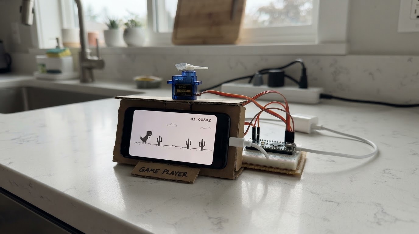
This project builds an automated player for the Chrome dinosaur game using an ESP32-CAM and a servo motor. The system uses the onboard camera to detect obstacles ahead of the dinosaur and triggers a servo-controlled key presser to make the dino jump at precisely the right moment.
The guide provides a complete parts list, wiring diagram showing servo and power connections, step-by-step assembly instructions for mounting the camera and servo arm, and the full firmware with obstacle detection logic. Builders will learn how to integrate computer vision with mechanical actuation on the ESP32 platform.
Wiring diagram

Gather all the parts
Assemble it in 5 steps
1. Prepare the camera board and servo arm
Use an AI Thinker ESP32-CAM board with its OV2640 camera attached. Fit the supplied servo horn (arm) to the SG90 servo, but do not force the screw or horn against the keyboard yet.
- A short, light horn works best. Add a small foam or felt pad to its tip so it does not scratch the Space bar.
- Place the camera about 15–30 cm from the screen and angle it toward the game area.
- Keep the camera lens and the game screen clean; glare or reflections can make obstacle detection unreliable.
2. Wire the servo signal
Connect the SG90 orange/yellow SIGNAL wire to ESP32-CAM GPIO16.
- GPIO16 is the free PWM pin selected for the servo.
- The ESP32-CAM camera pins are already used internally; do not connect the servo signal to them.
- Check the servo wire colors on your unit: orange/yellow is normally signal, red is normally 5 V, and brown/black is normally ground.
3. Make the shared 5 V power connections
Connect the regulated 5 V supply positive output to the ESP32-CAM 5V pin and the servo red VCC wire. Connect the supply ground to the ESP32-CAM GND pin and the servo brown/black GND wire.
- Use a supply rated for at least 1 A so the servo has enough current when it moves.
- All three grounds must meet: supply, ESP32-CAM, and servo.
- Use only regulated 5 V. Do not connect a 9 V battery or an unregulated supply to the 5V pin.
- Servo movement can cause resets with weak USB power; use the dedicated 5 V supply rather than powering the servo from a computer USB port.
4. Position the key-presser
Put the servo beside the keyboard so the horn rests above the center of the Space bar. After deploying, adjust the horn position mechanically so its press angle taps the key and its rest angle clears it.
- Use tape, a small clamp, or a simple bracket to stop the servo body from shifting.
- The servo should press briefly, then lift fully; it must not hold Space down.
- Switch off power before moving the servo horn by hand.
- Keep fingers clear during the first powered tests because the arm moves quickly.
5. Aim the camera at the game
Open the Chrome Dino game, keep its window and zoom level steady, and point the ESP32-CAM at the running Dino. The firmware watches a narrow area ahead of the Dino near the ground and taps Space when a dark obstacle enters that area.
- Use normal light mode with a bright background and dark Dino/cacti.
- Avoid changing browser zoom, moving the game window, or showing unrelated dark shapes inside the camera view after you have aimed it.
- This is an optical detector, not a direct computer connection. It may need small physical camera-position and servo-arm adjustments for your screen and keyboard.
Review all connections
1. Connections between "servo_supply" and "ESP32"
2. Connections between "space_servo" and "ESP32"
Deploy the firmware
#include <Arduino.h>
#include "esp_camera.h"
#include <ESP32Servo.h>

// AI Thinker ESP32-CAM fixed OV2640 wiring.
#define PWDN_GPIO_NUM     32
#define RESET_GPIO_NUM    -1
#define XCLK_GPIO_NUM      0
#define SIOD_GPIO_NUM     26
#define SIOC_GPIO_NUM     27
#define Y9_GPIO_NUM       35
#define Y8_GPIO_NUM       34
#define Y7_GPIO_NUM       39
#define Y6_GPIO_NUM       36
#define Y5_GPIO_NUM       21
#define Y4_GPIO_NUM       19
#define Y3_GPIO_NUM       18
#define Y2_GPIO_NUM        5
#define VSYNC_GPIO_NUM    25
#define HREF_GPIO_NUM     23
#define PCLK_GPIO_NUM     22


// Forward declarations
bool obstacleInView(const camera_fb_t *frame);
void jump();
bool initCamera();

constexpr int SERVO_PIN = 16;
constexpr int REST_ANGLE = 25;
constexpr int PRESS_ANGLE = 72;
constexpr uint16_t PRESS_TIME_MS = 85;
constexpr uint16_t RECOVER_TIME_MS = 260;

// Frame is 160 x 120. Aim this scan region just ahead of the Dino at ground level.
constexpr int ROI_LEFT = 82;
constexpr int ROI_RIGHT = 116;
constexpr int ROI_TOP = 70;
constexpr int ROI_BOTTOM = 104;
constexpr uint8_t DARK_THRESHOLD = 80;
constexpr uint8_t OBSTACLE_PERCENT = 8;

Servo spaceServo;
uint32_t lastJumpAt = 0;

bool obstacleInView(const camera_fb_t *frame) {
  if (frame == nullptr || frame->format != PIXFORMAT_GRAYSCALE) return false;

  const int left = constrain(ROI_LEFT, 0, frame->width - 1);
  const int right = constrain(ROI_RIGHT, left + 1, frame->width);
  const int top = constrain(ROI_TOP, 0, frame->height - 1);
  const int bottom = constrain(ROI_BOTTOM, top + 1, frame->height);
  uint32_t darkPixels = 0;
  const uint32_t totalPixels = (right - left) * (bottom - top);

  for (int y = top; y < bottom; ++y) {
    const uint8_t *row = frame->buf + y * frame->width;
    for (int x = left; x < right; ++x) {
      if (row[x] < DARK_THRESHOLD) ++darkPixels;
    }
  }
  return darkPixels * 100UL >= totalPixels * OBSTACLE_PERCENT;
}

void jump() {
  spaceServo.write(PRESS_ANGLE);
  delay(PRESS_TIME_MS);
  spaceServo.write(REST_ANGLE);
}

bool initCamera() {
  camera_config_t config = {};
  config.ledc_channel = LEDC_CHANNEL_0;
  config.ledc_timer = LEDC_TIMER_0;
  config.pin_d0 = Y2_GPIO_NUM;
  config.pin_d1 = Y3_GPIO_NUM;
  config.pin_d2 = Y4_GPIO_NUM;
  config.pin_d3 = Y5_GPIO_NUM;
  config.pin_d4 = Y6_GPIO_NUM;
  config.pin_d5 = Y7_GPIO_NUM;
  config.pin_d6 = Y8_GPIO_NUM;
  config.pin_d7 = Y9_GPIO_NUM;
  config.pin_xclk = XCLK_GPIO_NUM;
  config.pin_pclk = PCLK_GPIO_NUM;
  config.pin_vsync = VSYNC_GPIO_NUM;
  config.pin_href = HREF_GPIO_NUM;
  config.pin_sccb_sda = SIOD_GPIO_NUM;
  config.pin_sccb_scl = SIOC_GPIO_NUM;
  config.pin_pwdn = PWDN_GPIO_NUM;
  config.pin_reset = RESET_GPIO_NUM;
  config.xclk_freq_hz = 20000000;
  config.pixel_format = PIXFORMAT_GRAYSCALE;
  config.frame_size = FRAMESIZE_QQVGA;
  config.jpeg_quality = 12;
  config.fb_count = 1;
  config.grab_mode = CAMERA_GRAB_LATEST;
  return esp_camera_init(&config) == ESP_OK;
}

void setup() {
  Serial.begin(115200);
  spaceServo.setPeriodHertz(50);
  spaceServo.attach(SERVO_PIN, 500, 2400);
  spaceServo.write(REST_ANGLE);

  if (!initCamera()) {
    Serial.println("Camera initialization failed; check that this is an AI Thinker ESP32-CAM.");
    while (true) delay(1000);
  }
  Serial.println("Dino player ready. Aim the camera at the game, then adjust the servo arm.");
}

void loop() {
  camera_fb_t *frame = esp_camera_fb_get();
  if (frame == nullptr) return;
  const bool obstacle = obstacleInView(frame);
  esp_camera_fb_return(frame);

  const uint32_t now = millis();
  if (obstacle && now - lastJumpAt >= RECOVER_TIME_MS) {
    jump();
    lastJumpAt = now;
  }
  delay(12);
}
Remix this project
Make it yours in one click
Open a full copy of this project in your own Schematik workspace — diagram, code, parts, and assembly steps included. Swap the sensor, add features, or redesign the whole thing with AI. The author's original stays untouched.
Related projects

Create A Complete Electrical Schematic Esp32 Sma
ESP32 · September 17, 2026Ayansh Agrawal
ESP32 Kare Ekran Projeleri
ESP32 · September 16, 2026Seref Ai
Component Qty --------------------------- ------
ESP32 · September 16, 2026Yathartha Chakrawal