Community project
Matchbox Health Ecosystem Monitor
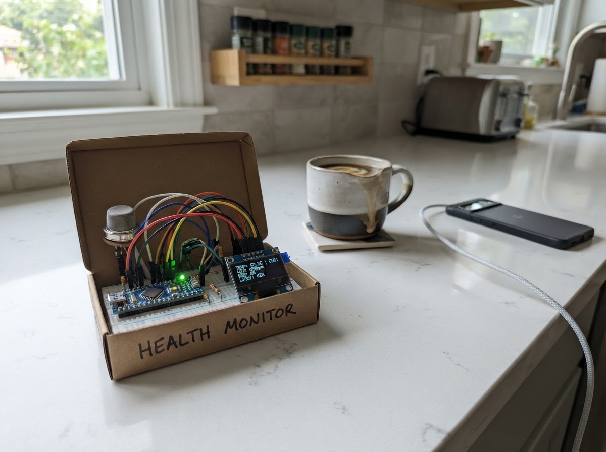
The Matchbox Health Ecosystem Monitor is a compact environmental and biometric sensor station built around the Raspberry Pi Pico. It combines gas detection, light sensing, and temperature monitoring into a single handheld device with real-time OLED display output, making it ideal for tracking air quality, ambient conditions, and environmental changes in a confined space.
This guide provides a complete wiring diagram, parts list, and step-by-step assembly instructions for building a tidy, modular sensor array. You'll learn how to integrate the MQ-2 gas sensor, CdS photoresistor, and temperature sensing circuit with the SSD1306 display, plus the firmware needed to read and display all sensor values on a compact screen.
Wiring diagram

Gather all the parts
Assemble it in 7 steps
1. Make an insulated wiring base
Cut a flat inner tray from a plastic bottle and secure the XIAO on it with double-sided tape, leaving its USB connector reachable. Add a second small plastic strip along one long edge as a cable channel. This keeps the copper loom away from the XIAO underside and makes the matchbox easy to close.
- Use narrow strips of electrical tape, heat-shrink, or short pieces of intact USB-cable insulation over every bare copper joint.
- Keep all sensor leads routed around the tray perimeter; keep the center of the tray clear.
- Do not let bare copper touch the XIAO, another wire, or the cardboard enclosure.
- Disconnect USB power before trimming, soldering, or rearranging wires.
2. Create short shared power and ground buses
Run one insulated 3V3 bus and one insulated GND bus along the plastic cable channel. Make the 3V3 bus only long enough to serve the OLED, NTC divider, LDR divider, and LED resistor. Make the GND bus serve the OLED, all three divider resistors, LED cathode, microswitch COM, and MQ-135 GND. Keep the separate 5V wire exclusively for MQ-135 VCC.
- Use black copper or black sleeving for GND; use red sleeving for 3V3; reserve another color, such as orange, for the MQ-135 5V lead.
- Join branches to the bus at one location rather than daisy-chaining through sensors.
- Never connect the MQ-135 5V VCC lead to the 3V3 bus.
- Verify all grounds share the same GND bus.
3. Mount and wire the front-panel controls
Mount the OLED behind the front window and place the mouse microswitch where its lever can be pressed through a small side opening. Route its four OLED wires together as one short flat bundle: VCC to 3V3, GND to GND, SDA to D4/GPIO6, and SCL to D5/GPIO7. Route the switch as a separate two-wire pair: COM to GND and NO to D10/GPIO3.
- Twist the SDA and SCL wires lightly together; keep this bundle short and away from the MQ heater wires.
- Label the switch terminals COM and NO before mounting; leave NC unused.
- Do not use the microswitch NC terminal.
- Do not power the OLED from 5V.
4. Build a compact analog-sensor strip
On a narrow plastic strip, mount the three 10k divider resistors and the MQ 39k/20k divider, keeping their junctions separate. Route each analog input as a short, labeled lead: MQ divider OUT to D0/GPIO26; NTC junction to D1/GPIO27; LDR junction to D2/GPIO28; soil divider OUT to D3/GPIO29. Use small tape flags labeled MQ, TEMP, PULSE, and SOIL at the XIAO end.
- Keep each analog junction physically short—ideally under 3 cm from its resistor—to reduce noise.
- Run the four ADC leads together down one side of the tray, separated from the OLED I2C bundle and the MQ 5V lead.
- Do not accidentally join the four analog junctions together.
- The MQ divider OUT is GPIO26; the soil divider OUT is GPIO29. These must remain separate.
5. Wire each sensor module with a tidy branch
Wire the NTC from 3V3 to its TEMP junction, with the 10k NTC divider resistor from that junction to GND. Wire the LDR from 3V3 to its PULSE junction, with its 10k resistor from that junction to GND. Wire the soil drive nail to D9/GPIO4; wire the other nail to the SOIL junction, whose 10k resistor goes to GND. Wire MQ-135 AO into the MQ divider VIN, divider GND to GND, and divider OUT to GPIO26.
- Twist the two soil-probe wires together from the box exit to the nails; add a knot or tape anchor inside the box for strain relief.
- Place the NTC and LDR lead pairs in their own small sleeves so they cannot snag when the drawer opens.
- Mount the MQ-135 at the ventilated end of the matchbox and keep its wiring on that side.
- MQ-135 AO must never connect directly to GPIO26; it must pass through the 39k/20k divider.
- Keep the warm MQ-135 module and its 5V lead away from the NTC touch pad and the cardboard.
6. Make the pulse sensor head a self-contained bundle
Mount the red LED and LDR facing the fingertip opening inside a black bottle-cap or tube. Connect LED anode to 3V3 through a 220 ohm series resistor and LED cathode to GND. Route the LDR pair beside the LED pair in a short four-wire bundle, then tape the bundle to the tray before it reaches the analog strip.
- Use opaque tape around the cap or tube to block room light.
- Keep the LED resistor close to the LED anode, not loose in the cable bundle.
- The red LED needs its 220 ohm series resistor.
- This is a classroom pulse-trend demonstration, not a medical measurement.
7. Anchor, inspect, and close the loom
Before closing the matchbox, tape or hot-glue each bundle to the plastic tray at two points: near the XIAO and near the sensor or enclosure exit. Leave a small service loop near the OLED and USB connector, but no loose wire loops elsewhere. Inspect that the OLED/I2C bundle, ADC bundle, MQ power lead, and soil-probe pair remain distinct. Then power from USB and close the enclosure gently without pinching wires.
- A simple color scheme makes judging easier: red = 3V3, orange = MQ 5V, black = GND, blue/green = I2C, white = analog signals, and yellow = GPIO4 soil drive.
- Use tape flags on both ends of any wire that crosses the tray.
- For the competition, leave the tray removable so judges can see the recycled wiring loom.
- Do not trap wires under the matchbox drawer edges.
- Check for copper whiskers and accidental shorts before reconnecting USB power.
- Keep the soil nails and all exposed copper away from anything except the intended moist-soil sample.
Review all connections
1. Connections between "oled_091" and "Raspberry Pi Pico"
2. Connections between "mq135_raw" and "Raspberry Pi Pico"
3. Connections between "mq135_divider" and "Raspberry Pi Pico"
4. Connections between "ntc_skin" and "Raspberry Pi Pico"
5. Connections between "ntc_divider" and "Raspberry Pi Pico"
6. Connections between "pulse_ldr" and "Raspberry Pi Pico"
7. Connections between "ldr_divider" and "Raspberry Pi Pico"
8. Connections between "soil_nails" and "Raspberry Pi Pico"
9. Connections between "soil_divider" and "Raspberry Pi Pico"
10. Connections between "page_switch" and "Raspberry Pi Pico"
11. Connections between "red_led" and "Raspberry Pi Pico"
Deploy the firmware
#include <Arduino.h>
#include <Wire.h>
#include <Adafruit_GFX.h>
#include <Adafruit_SSD1306.h>
#include <math.h>


// Forward declarations
int averageAnalog(uint8_t pin, uint8_t count);
float readSkinTemperatureC(int raw);
int readSoil();
void updatePulse(int sample);
void header(const __FlashStringHelper *title);
void drawPage();

constexpr uint8_t MQ_PIN = 26;
constexpr uint8_t NTC_PIN = 27;
constexpr uint8_t LDR_PIN = 28;
constexpr uint8_t SOIL_PIN = 29;
constexpr uint8_t SOIL_DRIVE_PIN = 4;
constexpr uint8_t BUTTON_PIN = 3;
constexpr uint8_t OLED_SDA_PIN = 6;
constexpr uint8_t OLED_SCL_PIN = 7;
constexpr uint8_t OLED_WIDTH = 128;
constexpr uint8_t OLED_HEIGHT = 32;
constexpr uint8_t OLED_ADDR = 0x3C;

Adafruit_SSD1306 display(OLED_WIDTH, OLED_HEIGHT, &Wire, -1);
uint8_t page = 0;
bool lastButton = HIGH;
uint32_t lastDebounceMs = 0;
uint32_t lastFastSampleMs = 0;
uint32_t lastSlowSampleMs = 0;
int mqRaw = 0, ntcRaw = 0, ldrRaw = 0, soilRaw = 0;
float skinC = NAN;
float bpm = NAN;
float ldrBaseline = 0.0f;
bool wasAbove = false;
uint32_t lastBeatMs = 0;

int averageAnalog(uint8_t pin, uint8_t count = 12) {
  uint32_t total = 0;
  for (uint8_t i = 0; i < count; ++i) {
    total += analogRead(pin);
    delay(2);
  }
  return total / count;
}

float readSkinTemperatureC(int raw) {
  if (raw < 4 || raw > 1019) return NAN;
  const float resistance = 10000.0f * (1023.0f / raw - 1.0f);
  return 1.0f / (1.0f / 298.15f + log(resistance / 10000.0f) / 3950.0f) - 273.15f;
}

int readSoil() {
  pinMode(SOIL_DRIVE_PIN, OUTPUT);
  digitalWrite(SOIL_DRIVE_PIN, HIGH);
  delay(8);
  int value = averageAnalog(SOIL_PIN, 8);
  digitalWrite(SOIL_DRIVE_PIN, LOW);
  pinMode(SOIL_DRIVE_PIN, INPUT);
  return value;
}

void updatePulse(int sample) {
  if (ldrBaseline == 0.0f) ldrBaseline = sample;
  ldrBaseline = ldrBaseline * 0.985f + sample * 0.015f;
  int threshold = max(8, (int)(ldrBaseline * 0.035f));
  bool above = abs(sample - (int)ldrBaseline) > threshold;
  uint32_t now = millis();
  if (above && !wasAbove && lastBeatMs != 0) {
    uint32_t interval = now - lastBeatMs;
    if (interval >= 350 && interval <= 1500) {
      float instantaneous = 60000.0f / interval;
      bpm = isnan(bpm) ? instantaneous : bpm * 0.70f + instantaneous * 0.30f;
    }
  }
  if (above && !wasAbove) lastBeatMs = now;
  wasAbove = above;
}

void header(const __FlashStringHelper *title) {
  display.setTextSize(1);
  display.setTextColor(SSD1306_WHITE);
  display.setCursor(0, 0);
  display.print(title);
  display.setCursor(108, 0);
  display.print(page + 1);
  display.print(F("/4"));
  display.drawLine(0, 9, 127, 9, SSD1306_WHITE);
}

void drawPage() {
  display.clearDisplay();
  if (page == 0) {
    header(F("AIR SAFETY"));
    display.setCursor(0, 13); display.print(F("MQ raw: ")); display.print(mqRaw);
    display.setCursor(0, 23);
    if (mqRaw < 300) display.print(F("Trend: cleaner air"));
    else if (mqRaw < 600) display.print(F("Trend: check airflow"));
    else display.print(F("Trend: smoke/gas high"));
  } else if (page == 1) {
    header(F("THERMAL HEALTH"));
    display.setCursor(0, 13); display.print(F("NTC raw: ")); display.print(ntcRaw);
    display.setCursor(0, 23);
    if (isnan(skinC)) display.print(F("Touch sensor to read"));
    else { display.print(F("Skin: ")); display.print(skinC, 1); display.print(F(" C")); }
  } else if (page == 2) {
    header(F("DIY HEART RATE"));
    display.setCursor(0, 13); display.print(F("LDR raw: ")); display.print(ldrRaw);
    display.setCursor(0, 23);
    if (isnan(bpm) || millis() - lastBeatMs > 3000) display.print(F("Cover LED+LDR w/finger"));
    else { display.print(F("Pulse: ")); display.print(bpm, 0); display.print(F(" BPM*")); }
  } else {
    header(F("AGRICULTURE"));
    display.setCursor(0, 13); display.print(F("Soil raw: ")); display.print(soilRaw);
    display.setCursor(0, 23);
    if (soilRaw < 300) display.print(F("Soil: dry"));
    else if (soilRaw < 650) display.print(F("Soil: moderate"));
    else display.print(F("Soil: wet"));
  }
  display.display();
}

void setup() {
  pinMode(BUTTON_PIN, INPUT_PULLUP);
  pinMode(SOIL_DRIVE_PIN, INPUT);
  analogReadResolution(10);
Wire.begin();
  if (!display.begin(SSD1306_SWITCHCAPVCC, OLED_ADDR)) while (true) delay(100);
  display.clearDisplay();
  display.setTextSize(1); display.setTextColor(SSD1306_WHITE);
  display.setCursor(0, 8); display.print(F("Eco + Health Analyzer"));
  display.setCursor(0, 20); display.print(F("Press mouse switch"));
  display.display();
  delay(1200);
  drawPage();
}

void loop() {
  uint32_t now = millis();
  bool button = digitalRead(BUTTON_PIN);
  if (lastButton == HIGH && button == LOW && now - lastDebounceMs > 180) {
    page = (page + 1) % 4;
    lastDebounceMs = now;
    drawPage();
  }
  lastButton = button;

  if (now - lastFastSampleMs >= 50) {
    ldrRaw = averageAnalog(LDR_PIN, 4);
    updatePulse(ldrRaw);
    lastFastSampleMs = now;
  }
  if (now - lastSlowSampleMs >= 1000) {
    mqRaw = averageAnalog(MQ_PIN);
    ntcRaw = averageAnalog(NTC_PIN);
    skinC = readSkinTemperatureC(ntcRaw);
    soilRaw = readSoil();
    lastSlowSampleMs = now;
    drawPage();
  }
}
Remix this project
Make it yours in one click
Open a full copy of this project in your own Schematik workspace — diagram, code, parts, and assembly steps included. Swap the sensor, add features, or redesign the whole thing with AI. The author's original stays untouched.
Related projects
Fridge Scale Smart Clip
Raspberry Pi Pico · September 14, 2026Phillip Knopp
Tiny Robot AI Assistant
Raspberry Pi Pico · September 13, 2026Shaikh Tajmul haque
Tiny Spider Robot
Raspberry Pi Pico · September 13, 2026Shaikh Tajmul haque