Community project
Semáforo Inteligente de Ruido
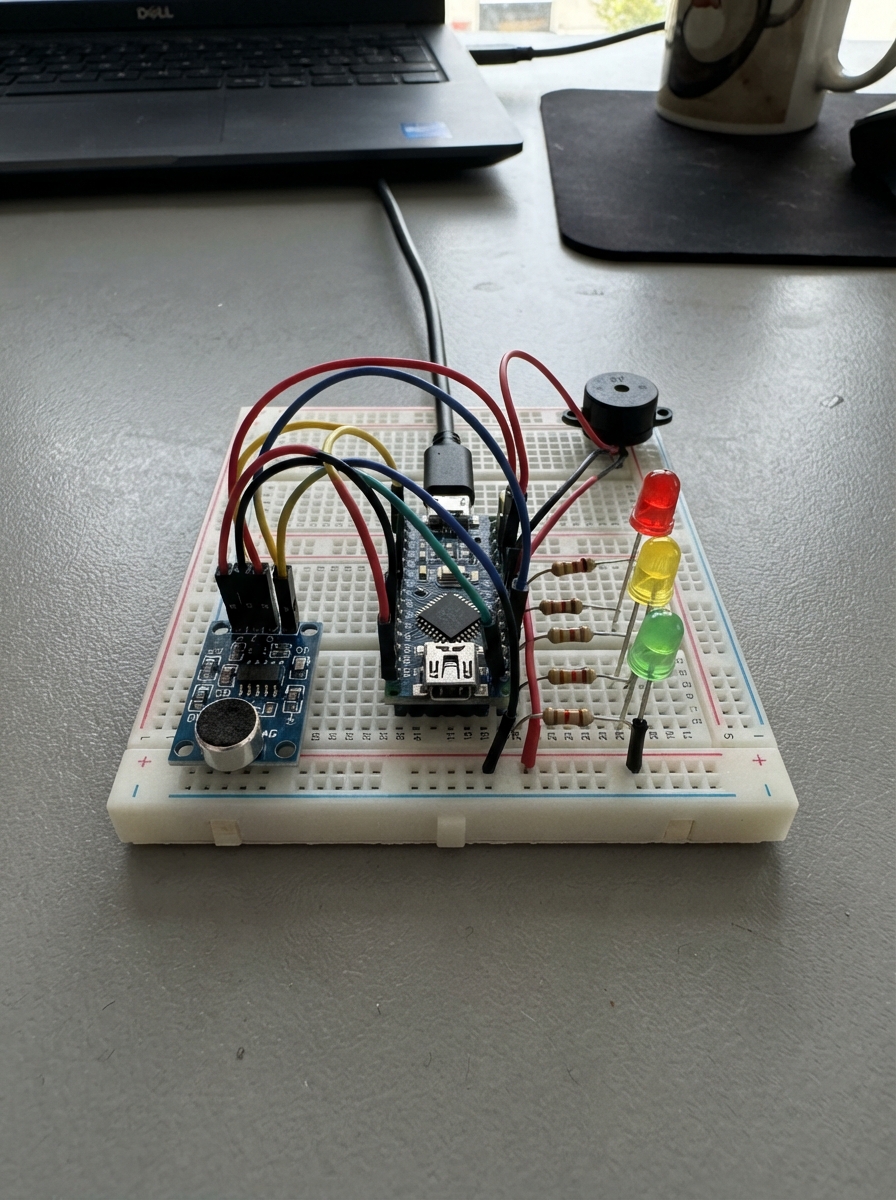
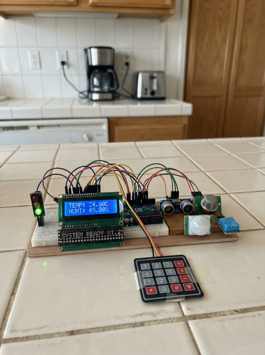
This intelligent noise traffic light uses a sound sensor to monitor ambient noise levels and display real-time feedback through a three-color LED indicator. The system lights up green for quiet environments, yellow for moderate noise, and red with an active buzzer alarm when noise levels become excessive—perfect for classrooms, libraries, or quiet zones that need visual and audio feedback.
Builders will receive a complete wiring diagram, parts list, and step-by-step assembly instructions for connecting the KY-037 sound sensor, three LEDs with resistors, and a 5V buzzer to an Arduino Uno. The included firmware reads smoothed sensor values, applies adjustable thresholds, and triggers the alarm only after sustained high noise detection, with calibration guidance via the Serial Monitor for accurate threshold tuning.
Wiring diagram

Gather all the parts
Assemble it in 6 steps
1. Prepara la protoboard sin alimentación
Coloca la protoboard de 400 puntos frente a ti y deja el Arduino desconectado del USB. Con cables Dupont, une el pin 5V del Arduino al carril rojo de la protoboard y un pin GND al carril azul o negro. Esos dos carriles repartirán la alimentación a todas las piezas.
- En una protoboard, los cinco agujeros de cada fila corta suelen estar unidos; la ranura central los separa.
- Si los carriles de alimentación están partidos por la mitad, une cada mitad con un cable corto del mismo color.
- No conectes todavía el USB: un cable puesto en el agujero equivocado no debe recibir corriente mientras montas.
2. Coloca y conecta el sensor de sonido
Inserta el módulo KY-037 en una zona libre de la protoboard donde puedas ver las letras de sus pines. Lleva VCC al carril de 5V, GND al carril de GND y AO al pin A0 del Arduino. Deja DO sin cable: este proyecto lee solamente AO.
- Usa rojo para 5V, negro para GND y otro color para AO; así será más fácil seguir cada cable.
- El pequeño potenciómetro del KY-037 no se usa para la lectura AO inicial; no hace falta ajustarlo.
- No intercambies VCC y GND: alimentar el módulo al revés puede dañarlo.
3. Monta el LED verde y su resistencia
Inserta el LED verde con sus dos patas en filas distintas. La pata larga es el lado positivo. Conecta D8 del Arduino a una pata de la resistencia de 220 Ω; conecta la otra pata de esa resistencia a la pata larga del LED. Conecta la pata corta del LED al carril GND.
- La resistencia puede ponerse en cualquiera de los dos lados del LED, pero debe quedar siempre en serie entre D8 y la pata larga.
- No cortes ni sueldes las patas: el montaje debe quedar completamente removible.
- No conectes el LED directamente entre D8 y GND: sin su resistencia puede dañarse el LED o el pin del Arduino.
4. Monta los LED amarillo y rojo
Repite el mismo montaje en filas separadas. Para el LED amarillo: D9 va a una resistencia de 220 Ω, la resistencia va a la pata larga y la pata corta va a GND. Para el LED rojo: D10 va a otra resistencia de 220 Ω, la resistencia va a la pata larga y la pata corta va a GND.
- Deja al menos una fila libre entre LED y LED para poder ver cada conexión.
- Los tres LED comparten el mismo carril GND, pero cada uno necesita su propia resistencia de 220 Ω.
- Si un LED no enciende, corta la alimentación y gira solo ese LED: las patas larga y corta pueden estar invertidas.
5. Conecta el buzzer activo
Inserta el buzzer activo en dos filas diferentes de la protoboard. Conecta su terminal marcado + al pin D11 del Arduino y su terminal marcado - al carril GND. Si el buzzer tiene una pata más larga, normalmente es la positiva; confirma también el símbolo + impreso en la pieza.
- El buzzer activo ya genera su propio tono al recibir HIGH; por eso no necesita una biblioteca ni un circuito adicional.
- Colócalo lejos del micrófono del KY-037 para que su propio sonido no mantenga la alarma encendida.
- No inviertas los terminales + y - del buzzer: puede no sonar o dañarse.
6. Revisa antes de conectar el USB
Comprueba que solo hay un cable en A0 desde AO del KY-037, que DO sigue libre, y que D8, D9, D10 y D11 no están unidos entre sí. Confirma también que todas las tierras llegan al mismo carril GND. Después conecta el Arduino al ordenador mediante USB.
- El USB alimenta el Arduino y, desde su pin 5V, el sensor. No necesitas pila, adaptador ni soldadura.
- Mantén el micrófono del sensor accesible para hacer pruebas con voz, palmas y ruido ambiental.
- Si notas calor, olor extraño o un componente se calienta, desconecta el USB inmediatamente y revisa VCC y GND.
Review all connections
1. Connections between "ky037_1" and "Arduino"
2. Connections between "resistor_green_1" and "Arduino"
3. Connections between "led_green_1" and "Arduino"
4. Connections between "resistor_yellow_1" and "Arduino"
5. Connections between "led_yellow_1" and "Arduino"
6. Connections between "resistor_red_1" and "Arduino"
7. Connections between "led_red_1" and "Arduino"
8. Connections between "buzzer_active_5v_1" and "Arduino"
Deploy the firmware
// Semáforo inteligente de ruido con KY-037 (salida AO)
// Los valores son niveles relativos, no decibelios reales.

const byte SOUND_PIN = A0;
const byte GREEN_LED_PIN = 8;
const byte YELLOW_LED_PIN = 9;
const byte RED_LED_PIN = 10;
const byte BUZZER_PIN = 11;

// AJUSTA ESTOS DOS LÍMITES después de observar el Monitor Serial.
// Valores menores que MEDIUM_THRESHOLD: nivel bajo.
// Valores desde MEDIUM_THRESHOLD hasta antes de HIGH_THRESHOLD: nivel medio.
// Valores iguales o mayores que HIGH_THRESHOLD: nivel alto.
int MEDIUM_THRESHOLD = 350;
int HIGH_THRESHOLD = 650;

const byte SAMPLE_COUNT = 16;                 // Varias muestras reducen cambios bruscos.
const unsigned long HIGH_HOLD_MS = 2000UL;    // Ruido alto continuo necesario para la alarma.
const unsigned long SERIAL_INTERVAL_MS = 200UL;

enum NoiseLevel { LOW_LEVEL, MEDIUM_LEVEL, HIGH_LEVEL };

unsigned long highStartedAt = 0;
unsigned long lastSerialAt = 0;
bool buzzerOn = false;

int readSmoothedSound() {
  long total = 0;
  for (byte i = 0; i < SAMPLE_COUNT; i++) {
    total += analogRead(SOUND_PIN);
  }
  return total / SAMPLE_COUNT;
}

NoiseLevel getNoiseLevel(int soundValue) {
  if (soundValue >= HIGH_THRESHOLD) {
    return HIGH_LEVEL;
  }
  if (soundValue >= MEDIUM_THRESHOLD) {
    return MEDIUM_LEVEL;
  }
  return LOW_LEVEL;
}

void setTrafficLight(NoiseLevel level) {
  digitalWrite(GREEN_LED_PIN, level == LOW_LEVEL ? HIGH : LOW);
  digitalWrite(YELLOW_LED_PIN, level == MEDIUM_LEVEL ? HIGH : LOW);
  digitalWrite(RED_LED_PIN, level == HIGH_LEVEL ? HIGH : LOW);
}

void updateBuzzer(NoiseLevel level, unsigned long now) {
  if (level == HIGH_LEVEL) {
    if (highStartedAt == 0) {
      highStartedAt = now;
    }
    if (now - highStartedAt >= HIGH_HOLD_MS) {
      buzzerOn = true;
    }
  } else {
    highStartedAt = 0;
    buzzerOn = false;
  }

  digitalWrite(BUZZER_PIN, buzzerOn ? HIGH : LOW);
}

const char* levelName(NoiseLevel level) {
  if (level == LOW_LEVEL) return "BAJO";
  if (level == MEDIUM_LEVEL) return "MEDIO";
  return "ALTO";
}

void setup() {
  pinMode(GREEN_LED_PIN, OUTPUT);
  pinMode(YELLOW_LED_PIN, OUTPUT);
  pinMode(RED_LED_PIN, OUTPUT);
  pinMode(BUZZER_PIN, OUTPUT);

  digitalWrite(BUZZER_PIN, LOW);
  Serial.begin(9600);
  Serial.println("Semaforo de ruido listo");
  Serial.println("Valor suavizado | Nivel | Alarma");
}

void loop() {
  unsigned long now = millis();
  int soundValue = readSmoothedSound();
  NoiseLevel level = getNoiseLevel(soundValue);

  setTrafficLight(level);
  updateBuzzer(level, now);

  if (now - lastSerialAt >= SERIAL_INTERVAL_MS) {
    lastSerialAt = now;
    Serial.print(soundValue);
    Serial.print(" | ");
    Serial.print(levelName(level));
    Serial.print(" | ");
    Serial.println(buzzerOn ? "ACTIVA" : "apagada");
  }
}
Remix this project
Make it yours in one click
Open a full copy of this project in your own Schematik workspace — diagram, code, parts, and assembly steps included. Swap the sensor, add features, or redesign the whole thing with AI. The author's original stays untouched.