Community project
Nivasa Pair Lock Prototype
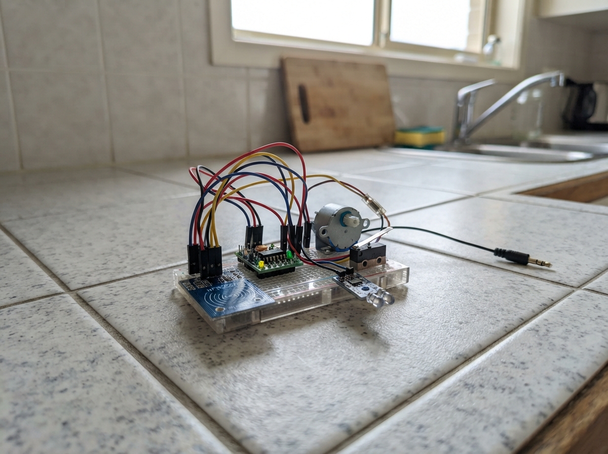
The Nivasa Pair Lock Prototype is an RFID-controlled electronic lock system built around an ESP32 microcontroller. It uses dual RFID readers to authenticate access attempts, a stepper motor to control a physical bolt mechanism, and multiple sensors to monitor door state, detect tampering, and trigger external devices like cameras.
This guide provides a complete wiring diagram, parts list, and step-by-step assembly instructions for building the lock prototype. The firmware handles RFID authentication across two zones, manages stepper motor movement with limit switches, monitors door and decoy sensors, and coordinates camera triggering. Builders will learn how to integrate multiple sensor types, manage separate power supplies safely, and calibrate the bolt travel distance for reliable operation.
Wiring diagram

Gather all the parts
Assemble it in 6 steps
1. Keep the two power supplies separate
Power the WeAct ESP32-C6-MiNi from its USB-C socket. Set the MB102 module to 5 V, then connect its 5 V and GND rails only to the ULN2003 board; do not connect its 5 V rail to the C6 3V3 pin. Power the ESP32-CAM from its own regulated 5 V, 2 A supply. Join the GND rail of the C6, MB102, and camera supply together so the trigger signal has the same zero-volt reference.
- Do not put 5 V on any ESP32-C6 GPIO or on either RC522 VCC pin — that can permanently damage the 3.3 V parts.
- Do not run the motor or camera from the C6 3V3 pin; their current demand can make the controller reset.
2. Wire the two card zones
Connect both RC522 readers to the C6 3V3 and GND rails: each VCC goes to 3V3 (power) and each GND goes to GND (ground). Join both readers' SCK pins to GPIO6 (clock), MOSI pins to GPIO7 (data to reader), and MISO pins to GPIO2 (data from reader). Connect zone A SDA/CS to GPIO18 (select zone A) and zone B SDA/CS to GPIO19 (select zone B). Tie both RST pins directly to 3V3 (keeps each reader enabled).
- RC522 modules are 3.3 V only; do not connect their VCC pins to 5 V.
- Keep the two reader antennas separated and preferably shielded by distance so a card is read by only the intended zone.
3. Connect the bolt motor and its end switches
Plug the 28BYJ-48 five-wire motor plug into the matching ULN2003 socket. Connect ULN2003 IN1 to GPIO10 (motor control), IN2 to GPIO11 (motor control), IN3 to GPIO16 (motor control), and IN4 to GPIO21 (motor control). Connect ULN2003 + to the MB102 5 V rail (motor power) and ULN2003 - to the shared GND rail (ground). For the bolt-out switch, connect COM to GND (ground) and NO to GPIO22 (end-stop signal). For the rack-home switch, connect COM to GND (ground) and NO to GPIO23 (end-stop signal).
- GPIO16 is used for ULN2003 IN3 because the requested GPIO14 is not available in the verified C6 board pin map.
- Press each switch by hand before mounting; the controller treats a pressed switch as a low signal.
- Mount the two end switches so the rack presses only one at a time. A missed end switch makes the controller stop after four seconds and report a jam.
4. Add the door, decoy, and hand sensors
Connect the MC-38 reed switch with one wire to GPIO0 (door signal) and the other wire to GND (ground). Connect the decoy keyhole microswitch COM to GND (ground) and its NO terminal to GPIO1 (tamper signal). Connect the IR module VCC to 3V3 (power), GND to GND (ground), and OUT to GPIO3 (hand-near signal).
- Use an IR module whose OUT pin never rises above 3.3 V. A 5 V-powered module can put 5 V on GPIO3 and damage the C6.
- GPIO0 is a boot-related input on some C6 setups: ensure the reed switch is open when you plug in or reset the board.
5. Join the camera trigger wire
Connect the C6 camera-trigger lead from GPIO20 to the AI Thinker ESP32-CAM header GPIO13 (photo signal). Connect a second wire from C6 GND to ESP32-CAM GND (shared ground). The camera sketch uses GPIO13 as an input with a pull-down, so it takes one picture when it receives the 200 ms high pulse.
- GPIO13 on the ESP32-CAM is also a microSD line. Leave the SD socket unused for this no-SD camera build.
6. Set safe travel before fitting the bolt
With the rack free to move, use the C6 USB serial console and send `cmd unlock` and `cmd lock`. Confirm the motor moves toward the home and bolt-out switches respectively. If either direction is wrong, swap the direction by changing the two `startMove` speed signs in the code before attaching the rack. Adjust `STEPS_PER_TRAVEL` only after the end switches are mechanically reliable.
- Do not test the mechanism against a closed door until both limit switches stop the motor correctly; a stalled 28BYJ-48 or rack can strip gears or bend the prototype mount.
Review all connections
1. Connections between "rc522_zone_a" and "ESP32"
2. Connections between "rc522_zone_b" and "ESP32"
3. Connections between "uln2003_1" and "ESP32"
4. Connections between "bolt_out_limit" and "ESP32"
5. Connections between "rack_home_limit" and "ESP32"
6. Connections between "door_reed_mc38" and "ESP32"
7. Connections between "decoy_keyhole_switch" and "ESP32"
8. Connections between "ir_proximity_3v3" and "ESP32"
9. Connections between "camera_trigger_output" and "ESP32"
Deploy the firmware
#include <Arduino.h>
#include <SPI.h>
#include <MFRC522.h>
#include <AccelStepper.h>
#include "hub_stubs.h"

// WeAct ESP32-C6-MiNi wiring. GPIO16 replaces the requested GPIO14 because
// GPIO14 is not broken out in the verified board pin map.
constexpr uint8_t RC522_SCK = 6;
constexpr uint8_t RC522_MISO = 2;
constexpr uint8_t RC522_MOSI = 7;
constexpr uint8_t RC522_ZONE_A_CS = 18;
constexpr uint8_t RC522_ZONE_B_CS = 19;
constexpr uint8_t STEPPER_IN1 = 10;
constexpr uint8_t STEPPER_IN2 = 11;
constexpr uint8_t STEPPER_IN3 = 16;
constexpr uint8_t STEPPER_IN4 = 21;
constexpr uint8_t BOLT_OUT_LIMIT = 22;
constexpr uint8_t RACK_HOME_LIMIT = 23;
constexpr uint8_t DOOR_REED = 0;
constexpr uint8_t DECOY_SWITCH = 1;
constexpr uint8_t IR_PROXIMITY = 3;
constexpr uint8_t CAMERA_TRIGGER = 20;

constexpr bool IR_ACTIVE_LOW = true;
constexpr long STEPS_PER_TRAVEL = 4096;  // Tune only after the rack is installed.
constexpr float STEPPER_SPEED = 700.0f;
constexpr uint32_t MOVE_TIMEOUT_MS = 4000;
constexpr uint32_t ACCESS_WINDOW_MS = 5000;
constexpr uint32_t HOME_RELOCK_MS = 30000;
constexpr uint32_t CAMERA_PULSE_MS = 200;
constexpr uint32_t SWITCH_DEBOUNCE_MS = 40;

MFRC522 readerA(RC522_ZONE_A_CS, MFRC522::UNUSED_PIN);
MFRC522 readerB(RC522_ZONE_B_CS, MFRC522::UNUSED_PIN);
// 28BYJ-48 half-step order for a ULN2003 board is IN1, IN3, IN2, IN4.
AccelStepper bolt(AccelStepper::HALF4WIRE, STEPPER_IN1, STEPPER_IN3, STEPPER_IN2, STEPPER_IN4);

enum Mode { HOME, NIGHT, AWAY, ALARM, SMOKE };
enum Motion { STOPPED, EXTENDING, RETRACTING };
enum Zone { NO_ZONE, ZONE_A, ZONE_B };

Mode mode = HOME;
Motion motion = STOPPED;
Zone firstZone = NO_ZONE;
Zone lastCardZone = NO_ZONE;
bool boltOut = false;
bool accessWindow = false;
bool relockPending = false;
bool cameraHigh = false;
bool lastDoorOpen = false;
bool lastDecoyPressed = false;
bool lastHandNear = false;
uint32_t accessStartedAt = 0;
uint32_t motionStartedAt = 0;
uint32_t unlockedAt = 0;
uint32_t cameraStartedAt = 0;
uint32_t lastDoorChangeAt = 0;
uint32_t lastDecoyChangeAt = 0;

struct KnownCard { const char *uid; const char *name; };
// Replace these placeholder UID strings with the uppercase values printed for your cards.
const KnownCard KNOWN_CARDS[] = {
  {"DE AD BE EF", "test-card-1"},
  {"12 34 56 78", "test-card-2"}
};
constexpr size_t KNOWN_CARD_COUNT = sizeof(KNOWN_CARDS) / sizeof(KNOWN_CARDS[0]);

const char *modeName(Mode value) {
  switch (value) {
    case HOME: return "Home"; case NIGHT: return "Night"; case AWAY: return "Away";
    case ALARM: return "Alarm"; case SMOKE: return "Smoke";
  }
  return "Unknown";
}

const char *zoneName(Zone value) {
  if (value == ZONE_A) return "A";
  if (value == ZONE_B) return "B";
  return "none";
}

bool doorOpen() { return digitalRead(DOOR_REED) == HIGH; }
bool handNear() { return digitalRead(IR_PROXIMITY) == (IR_ACTIVE_LOW ? LOW : HIGH); }
bool boltAtOutLimit() { return digitalRead(BOLT_OUT_LIMIT) == LOW; }
bool boltAtHomeLimit() { return digitalRead(RACK_HOME_LIMIT) == LOW; }

void releaseCoils() {
  bolt.disableOutputs();
}

void cameraPulse() {
  digitalWrite(CAMERA_TRIGGER, HIGH);
  cameraHigh = true;
  cameraStartedAt = millis();
}

void reportState() {
  Serial.printf("STATE mode=%s bolt=%s door=%s last_zone=%s hub=%s\n",
                modeName(mode), boltOut ? "out" : "home", doorOpen() ? "open" : "shut",
                zoneName(lastCardZone), getState());
}

void startMove(Motion nextMotion) {
  if (nextMotion == EXTENDING && boltAtOutLimit()) { boltOut = true; motion = STOPPED; releaseCoils(); return; }
  if (nextMotion == RETRACTING && boltAtHomeLimit()) { boltOut = false; motion = STOPPED; releaseCoils(); return; }
  motion = nextMotion;
  motionStartedAt = millis();
  bolt.enableOutputs();
  bolt.setSpeed(nextMotion == EXTENDING ? STEPPER_SPEED : -STEPPER_SPEED);
  sendEvent(nextMotion == EXTENDING ? "bolt_extending" : "bolt_retracting");
}

void stopMoveAtLimit(bool out) {
  motion = STOPPED;
  boltOut = out;
  releaseCoils();
  sendEvent(out ? "bolt_out" : "bolt_home");
  reportState();
}

void serviceBolt() {
  if (motion == STOPPED) return;
  if ((motion == EXTENDING && boltAtOutLimit()) || (motion == RETRACTING && boltAtHomeLimit())) {
    stopMoveAtLimit(motion == EXTENDING);
    return;
  }
  if (millis() - motionStartedAt >= MOVE_TIMEOUT_MS) {
    motion = STOPPED;
    releaseCoils();
    sendEvent("jam");
    Serial.println("JAM: neither end switch closed within 4 seconds.");
    return;
  }
  bolt.runSpeed();
}

String uidString(MFRC522 &reader) {
  String uid;
  for (byte i = 0; i < reader.uid.size; ++i) {
    if (i) uid += ' ';
    if (reader.uid.uidByte[i] < 0x10) uid += '0';
    uid += String(reader.uid.uidByte[i], HEX);
  }
  uid.toUpperCase();
  return uid;
}

bool isKnown(const String &uid) {
  for (size_t i = 0; i < KNOWN_CARD_COUNT; ++i) if (uid == KNOWN_CARDS[i].uid) return true;
  return false;
}

void finishRead(MFRC522 &reader) {
  reader.PICC_HaltA();
  reader.PCD_StopCrypto1();
}

void acceptZone(Zone zone) {
  lastCardZone = zone;
  Serial.printf("Known card accepted at zone %s\n", zoneName(zone));
  if (mode == HOME) {
    if (zone == ZONE_A) {
      startMove(RETRACTING);
      relockPending = true;
      unlockedAt = millis();
    }
    return;
  }
  if (mode != AWAY && mode != NIGHT) return;
  if (firstZone == NO_ZONE) {
    firstZone = zone;
    accessStartedAt = millis();
    Serial.printf("First factor: zone %s. Present the other zone within 5 seconds.\n", zoneName(zone));
    return;
  }
  if (firstZone == zone) return;
  if (firstZone == ZONE_B && zone == ZONE_A) sendEvent("duress");
  else sendEvent("authorized_entry");
  startMove(RETRACTING);
  firstZone = NO_ZONE;
  accessWindow = false;
}

void pollReader(MFRC522 &reader, Zone zone) {
  if (!reader.PICC_IsNewCardPresent() || !reader.PICC_ReadCardSerial()) return;
  const String uid = uidString(reader);
  if (isKnown(uid)) acceptZone(zone);
  else Serial.printf("Unknown UID at zone %s: %s\n", zoneName(zone), uid.c_str());
  finishRead(reader);
}

void serviceAccess() {
  const bool near = handNear();
  if (near && !lastHandNear) {
    accessWindow = true;
    accessStartedAt = millis();
    firstZone = NO_ZONE;
    cameraPulse();
    sendEvent("person_at_door");
  }
  lastHandNear = near;
  if (!accessWindow) return;
  if (millis() - accessStartedAt >= ACCESS_WINDOW_MS) {
    accessWindow = false;
    firstZone = NO_ZONE;
    return;
  }
  pollReader(readerA, ZONE_A);
  pollReader(readerB, ZONE_B);
}

void serviceInputs() {
  const bool nowDoorOpen = doorOpen();
  if (nowDoorOpen != lastDoorOpen && millis() - lastDoorChangeAt >= SWITCH_DEBOUNCE_MS) {
    lastDoorOpen = nowDoorOpen;
    lastDoorChangeAt = millis();
    if (nowDoorOpen) { sendEvent("door_open"); cameraPulse(); }
    else sendEvent("door_shut");
  }
  const bool decoyPressed = digitalRead(DECOY_SWITCH) == LOW;
  if (decoyPressed && !lastDecoyPressed && millis() - lastDecoyChangeAt >= SWITCH_DEBOUNCE_MS) {
    lastDecoyChangeAt = millis();
    sendEvent("tamper");
    cameraPulse();
    if (mode == AWAY || mode == NIGHT) sendEvent("alarm_requested");
  }
  lastDecoyPressed = decoyPressed;
}

void serviceRelock() {
  if (!relockPending || motion != STOPPED) return;
  // The 30-second clock starts only after the door is shut.
  if (doorOpen()) {
    unlockedAt = millis();
    return;
  }
  if (millis() - unlockedAt >= HOME_RELOCK_MS) {
    startMove(EXTENDING);
    relockPending = false;
  }
}

void setMode(Mode nextMode) {
  mode = nextMode;
  onMode(modeName(mode));
  if (mode == SMOKE) startMove(RETRACTING);
  reportState();
}

void handleSerial() {
  if (!Serial.available()) return;
  String line = Serial.readStringUntil('\n');
  line.trim(); line.toLowerCase();
  if (line == "mode home") setMode(HOME);
  else if (line == "mode night") setMode(NIGHT);
  else if (line == "mode away") setMode(AWAY);
  else if (line == "mode alarm") setMode(ALARM);
  else if (line == "mode smoke") setMode(SMOKE);
  else if (line == "cmd lock") { onCommand("lock"); startMove(EXTENDING); }
  else if (line == "cmd unlock") { onCommand("unlock"); startMove(RETRACTING); }
  else if (line == "state") reportState();
  else Serial.println("Commands: mode home|night|away|alarm|smoke, cmd lock|unlock, state");
}

void setup() {
  Serial.begin(115200);
  pinMode(BOLT_OUT_LIMIT, INPUT_PULLUP); pinMode(RACK_HOME_LIMIT, INPUT_PULLUP);
  pinMode(DOOR_REED, INPUT_PULLUP); pinMode(DECOY_SWITCH, INPUT_PULLUP);
  pinMode(IR_PROXIMITY, INPUT_PULLUP); pinMode(CAMERA_TRIGGER, OUTPUT);
  digitalWrite(CAMERA_TRIGGER, LOW);
  pinMode(RC522_ZONE_A_CS, OUTPUT); pinMode(RC522_ZONE_B_CS, OUTPUT);
  digitalWrite(RC522_ZONE_A_CS, HIGH); digitalWrite(RC522_ZONE_B_CS, HIGH);
  SPI.begin(RC522_SCK, RC522_MISO, RC522_MOSI, RC522_ZONE_A_CS);
  readerA.PCD_Init(); readerB.PCD_Init();
  bolt.setMaxSpeed(STEPPER_SPEED); bolt.setSpeed(STEPPER_SPEED); releaseCoils();
  boltOut = boltAtOutLimit(); lastDoorOpen = doorOpen(); lastHandNear = handNear();
  Serial.println("Nivasa Pair lock controller ready.");
  reportState();
}

void loop() {
  handleSerial();
  serviceInputs();
  serviceAccess();
  serviceBolt();
  serviceRelock();
  if (cameraHigh && millis() - cameraStartedAt >= CAMERA_PULSE_MS) { digitalWrite(CAMERA_TRIGGER, LOW); cameraHigh = false; }
}
Remix this project
Make it yours in one click
Open a full copy of this project in your own Schematik workspace — diagram, code, parts, and assembly steps included. Swap the sensor, add features, or redesign the whole thing with AI. The author's original stays untouched.