Community project
Nivasa Smart Gate Lock
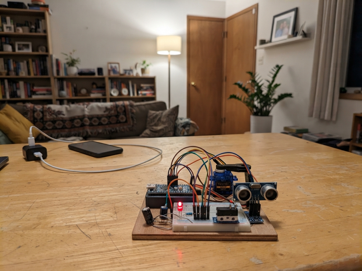
The Nivasa Smart Gate Lock is an intelligent access control system built around an ESP32 that combines mechanical and electronic security. It uses two servo motors to control a pawl and deadlock mechanism, while a suite of sensors—including an ultrasonic distance sensor, reed switch, vibration detector, and limit switches—monitor the gate state and detect tampering attempts. The system also includes an onboard camera for visual verification of access events.
This guide provides everything needed to assemble and deploy the lock: a complete wiring diagram showing power distribution from the LiPo battery through the UBEC regulator, sensor and actuator connections, and camera integration. You'll also get a detailed parts list, step-by-step assembly instructions covering the fused power input and sensor calibration, and the Arduino firmware that manages servo control, sensor monitoring, and Thread network communication for remote operation.
Wiring diagram

Gather all the parts
Assemble it in 6 steps
1. Make the fused battery input
With the rocker switch OFF, connect the 2S battery pack positive lead to the IN side of the 5 A fuse holder. Connect the fuse holder OUT side to the rocker-switch IN terminal. Connect the rocker-switch OUT terminal to UBEC VIN+. Connect the battery negative lead directly to UBEC VIN-. The battery balance plug is left unconnected during normal use; connect it only to a proper 2S LiPo balance charger when the system is switched off.
- Use connectors rated for the battery current and keep the battery wires short and thick.
- Set the UBEC output selector to exactly 5.0 V before connecting any electronics.
- Never connect the 7.4–8.4 V battery directly to a servo, ESP32-CAM, HC-SR04, or C6 board — it can permanently damage them.
- A LiPo battery can deliver enough current to melt thin wires. Keep the fuse close to the battery positive lead and never bypass it.
- Charge the pack only with a 2S balance charger, on a non-flammable surface, while attended.
2. Check the regulated 5 V rail first
Turn the switch ON with no electronics connected. Measure between UBEC VOUT+ and VOUT- with a multimeter and confirm it is 5.0 V. Turn the switch OFF, then use UBEC VOUT+ as the 5 V breadboard rail and UBEC VOUT- as the shared ground rail.
- Mark the 5 V rail with red tape and the ground rail with black tape so they cannot be mixed up.
- Do not continue if the meter shows more than 5.25 V; adjust or replace the regulator before connecting the boards.
3. Power the boards from the battery rail
Connect UBEC VOUT+ to ESP32-CAM 5V and connect UBEC VOUT- to ESP32-CAM GND. Connect the same 5 V and ground rails to a short USB-C power lead or USB-C breakout that plugs into the C6 USB-C port; this supplies the C6 from the battery. Do not connect a phone charger at the same time. Join the C6 ground to the common ground rail.
- Use the C6 USB-C port for the normal battery feed so its onboard 3.3 V regulator supplies the C6 logic safely.
- Connect USB-C to a computer only temporarily for flashing, with the battery switch OFF.
- Never feed the UBEC 5 V rail into the C6 3V3 pin — that bypasses its regulator and can damage the C6.
- Do not power the C6 from its USB-C battery lead and a computer USB port at the same time unless the lead is specifically made for safe power isolation.
4. Wire the servos and capacitor
Connect both SG90 red wires to the regulated 5 V rail and both brown or black wires to the shared ground rail. Connect the pawl servo orange signal wire to C6 GPIO18 and the deadlock servo orange signal wire to C6 GPIO19. Put the 470 µF capacitor across the same 5 V and ground rails: its long positive lead goes to 5 V and its striped negative lead goes to ground.
- Place the capacitor physically close to the servo connectors so it helps when a servo begins moving.
- The capacitor is polarized; reversed power can make it overheat or burst.
- Do not run servo power through the breadboard’s thin power strips if the servos bind; use direct, suitably thick wires from the UBEC rail.
5. Wire the sensors, switches, and status lights
Connect HC-SR04 VCC to 5 V, GND to ground, and TRIG to C6 GPIO20. Make the ECHO divider: ECHO to the 1 kΩ resistor, its other end to GPIO21 and to one end of the 2 kΩ resistor, then the free 2 kΩ end to ground. Connect the MC-38 between GPIO10 and ground. Connect SW-420 VCC to C6 3V3, GND to ground, and DO to GPIO2. Connect each limit switch COM to ground; connect hook NO to GPIO3 and inside-lever NO to GPIO11. Wire GPIO6 through 330 Ω to the green LED long leg and its short leg to ground; wire GPIO7 through 330 Ω to the red LED long leg and its short leg to ground.
- The switches use the C6 internal pull-up, so closing a switch to ground is the active state.
- Never connect HC-SR04 ECHO directly to GPIO21 — its 5 V output can damage the 3.3 V C6 input.
- Keep SW-420 VCC at 3.3 V because its DO output otherwise may be too high for the C6.
6. Connect the camera trigger and test safely
Connect C6 GPIO22 directly to ESP32-CAM GPIO13. With both servo horns removed, turn on the battery switch. Confirm the 5 V rail remains stable, then test the LEDs, sensors, and camera trigger before fitting the servo horns to the lock mechanism.
- A brief camera trigger is normal when the gate event occurs. Set the servo horns only after you confirm the 0 degree positions do not force the lock mechanism.
- This breadboard prototype is not weatherproof or security-grade; do not rely on it as the sole lock on a real gate.
- Turn the battery switch OFF before moving wires or changing the servo linkage.
Review all connections
1. Connections between "servo_pawl" and "ESP32"
2. Connections between "servo_deadlock" and "ESP32"
3. Connections between "ultrasonic" and "ESP32"
4. Connections between "echo_top_resistor" and "ESP32"
5. Connections between "echo_bottom_resistor" and "ESP32"
6. Connections between "reed_gate" and "ESP32"
7. Connections between "vibration" and "ESP32"
8. Connections between "hook_limit" and "ESP32"
9. Connections between "inside_limit" and "ESP32"
10. Connections between "green_led" and "ESP32"
11. Connections between "green_resistor" and "ESP32"
12. Connections between "red_led" and "ESP32"
13. Connections between "red_resistor" and "ESP32"
14. Connections between "servo_bulk_capacitor" and "ESP32"
15. Connections between "camera_board" and "ESP32"
16. Connections between "gate_battery" and "ESP32"
17. Connections between "power_ubec" and "ESP32"
18. Connections between "battery_fuse" and "ESP32"
19. Connections between "battery_switch" and "ESP32"
Deploy the firmware
#include <Arduino.h>
#include <ESP32Servo.h>
#include <OThread.h>

// Replace these placeholders with your Thread network's active dataset.
static const char *THREAD_NETWORK_NAME = "REPLACE_WITH_THREAD_NETWORK_NAME";
static const uint8_t THREAD_NETWORK_KEY[16] = {0, 0, 0, 0, 0, 0, 0, 0, 0, 0, 0, 0, 0, 0, 0, 0};
static const uint8_t THREAD_EXT_PAN_ID[8] = {0, 0, 0, 0, 0, 0, 0, 0};
static const uint16_t THREAD_PAN_ID = 0x1234;
static const uint8_t THREAD_CHANNEL = 15;
// This board package exposes Thread startup but not the newer public CoAP/UDP wrapper headers.

constexpr int PAWL_SERVO_PIN = 18;
constexpr int DEADLOCK_SERVO_PIN = 19;
constexpr int SONAR_TRIG_PIN = 20;
constexpr int SONAR_ECHO_PIN = 21;
constexpr int REED_PIN = 10;
constexpr int VIBRATION_PIN = 2;
constexpr int HOOK_LIMIT_PIN = 3;
constexpr int INSIDE_LIMIT_PIN = 11;
constexpr int CAMERA_TRIGGER_PIN = 22;
constexpr int GREEN_LED_PIN = 6;
constexpr int RED_LED_PIN = 7;
constexpr uint32_t RELEASE_MS = 5000;
constexpr uint32_t CAMERA_PULSE_MS = 200;
constexpr uint32_t NEAR_HOLD_MS = 1000;
constexpr uint32_t SONAR_PERIOD_MS = 100;

Servo pawlServo;
Servo deadlockServo;
bool deadlocked = false;
bool pawlReleased = false;
bool cameraPulseActive = false;
uint32_t releaseStartedAt = 0;
uint32_t cameraPulseStartedAt = 0;
uint32_t nearStartedAt = 0;
uint32_t lastSonarAt = 0;
String lastEvent = "boot";

bool activeLow(int pin) { return digitalRead(pin) == LOW; }
void updateIndicators() {
  digitalWrite(GREEN_LED_PIN, pawlReleased ? HIGH : LOW);
  digitalWrite(RED_LED_PIN, (!pawlReleased || deadlocked) ? HIGH : LOW);
}
void setDeadlock(bool enabled) {
  deadlocked = enabled;
  deadlockServo.write(enabled ? 90 : 0);
  if (enabled && pawlReleased) { pawlReleased = false; pawlServo.write(0); }
  updateIndicators();
}
void releasePawl() {
  if (deadlocked) { lastEvent = "release_blocked_deadlocked"; return; }
  pawlReleased = true;
  releaseStartedAt = millis();
  pawlServo.write(90);
  lastEvent = "released";
  updateIndicators();
}
void triggerCamera(const char *eventName) {
  lastEvent = eventName;
  if (!cameraPulseActive) {
    digitalWrite(CAMERA_TRIGGER_PIN, HIGH);
    cameraPulseStartedAt = millis();
    cameraPulseActive = true;
  }
  Serial.printf("EVENT %s gate_shut=%d hook_home=%d deadlock=%d\n", eventName, activeLow(REED_PIN), activeLow(HOOK_LIMIT_PIN), deadlocked);
}
float readDistanceCm() {
  digitalWrite(SONAR_TRIG_PIN, LOW);
  delayMicroseconds(2);
  digitalWrite(SONAR_TRIG_PIN, HIGH);
  delayMicroseconds(10);
  digitalWrite(SONAR_TRIG_PIN, LOW);
  unsigned long pulse = pulseIn(SONAR_ECHO_PIN, HIGH, 30000);
  return pulse ? pulse * 0.0343f * 0.5f : -1.0f;
}
void startThread() {
  OThread.begin(false);
  DataSet dataset;
  dataset.setNetworkName(THREAD_NETWORK_NAME);
  dataset.setNetworkKey(THREAD_NETWORK_KEY);
  dataset.setExtendedPanId(THREAD_EXT_PAN_ID);
  dataset.setPanId(THREAD_PAN_ID);
  dataset.setChannel(THREAD_CHANNEL);
  OThread.commitDataSet(dataset);
  OThread.networkInterfaceUp();
  OThread.start();
}
void setup() {
  Serial.begin(115200);
  pinMode(SONAR_TRIG_PIN, OUTPUT);
  pinMode(SONAR_ECHO_PIN, INPUT);
  pinMode(REED_PIN, INPUT_PULLUP);
  pinMode(VIBRATION_PIN, INPUT);
  pinMode(HOOK_LIMIT_PIN, INPUT_PULLUP);
  pinMode(INSIDE_LIMIT_PIN, INPUT_PULLUP);
  pinMode(CAMERA_TRIGGER_PIN, OUTPUT);
  pinMode(GREEN_LED_PIN, OUTPUT);
  pinMode(RED_LED_PIN, OUTPUT);
  digitalWrite(CAMERA_TRIGGER_PIN, LOW);
  pawlServo.setPeriodHertz(50);
  deadlockServo.setPeriodHertz(50);
  pawlServo.attach(PAWL_SERVO_PIN, 500, 2400);
  deadlockServo.attach(DEADLOCK_SERVO_PIN, 500, 2400);
  pawlServo.write(0);
  deadlockServo.write(0);
  updateIndicators();
  startThread();
}
void loop() {
  uint32_t now = millis();
  if (pawlReleased && now - releaseStartedAt >= RELEASE_MS) {
    pawlReleased = false;
    pawlServo.write(0);
    lastEvent = "release_timeout_locked";
    updateIndicators();
  }
  if (cameraPulseActive && now - cameraPulseStartedAt >= CAMERA_PULSE_MS) {
    digitalWrite(CAMERA_TRIGGER_PIN, LOW);
    cameraPulseActive = false;
  }
  if (digitalRead(VIBRATION_PIN) == HIGH) {
    setDeadlock(true);
    triggerCamera("forced");
    delay(100);
  }
  if (now - lastSonarAt >= SONAR_PERIOD_MS) {
    lastSonarAt = now;
    float cm = readDistanceCm();
    if (cm > 0 && cm < 150.0f) {
      if (nearStartedAt == 0) nearStartedAt = now;
      if (now - nearStartedAt >= NEAR_HOLD_MS) {
        triggerCamera("at_gate");
        nearStartedAt = now + 60000UL;
      }
    } else {
      nearStartedAt = 0;
    }
  }
}
Remix this project
Make it yours in one click
Open a full copy of this project in your own Schematik workspace — diagram, code, parts, and assembly steps included. Swap the sensor, add features, or redesign the whole thing with AI. The author's original stays untouched.