Community project
Obstacle-Avoiding Rover
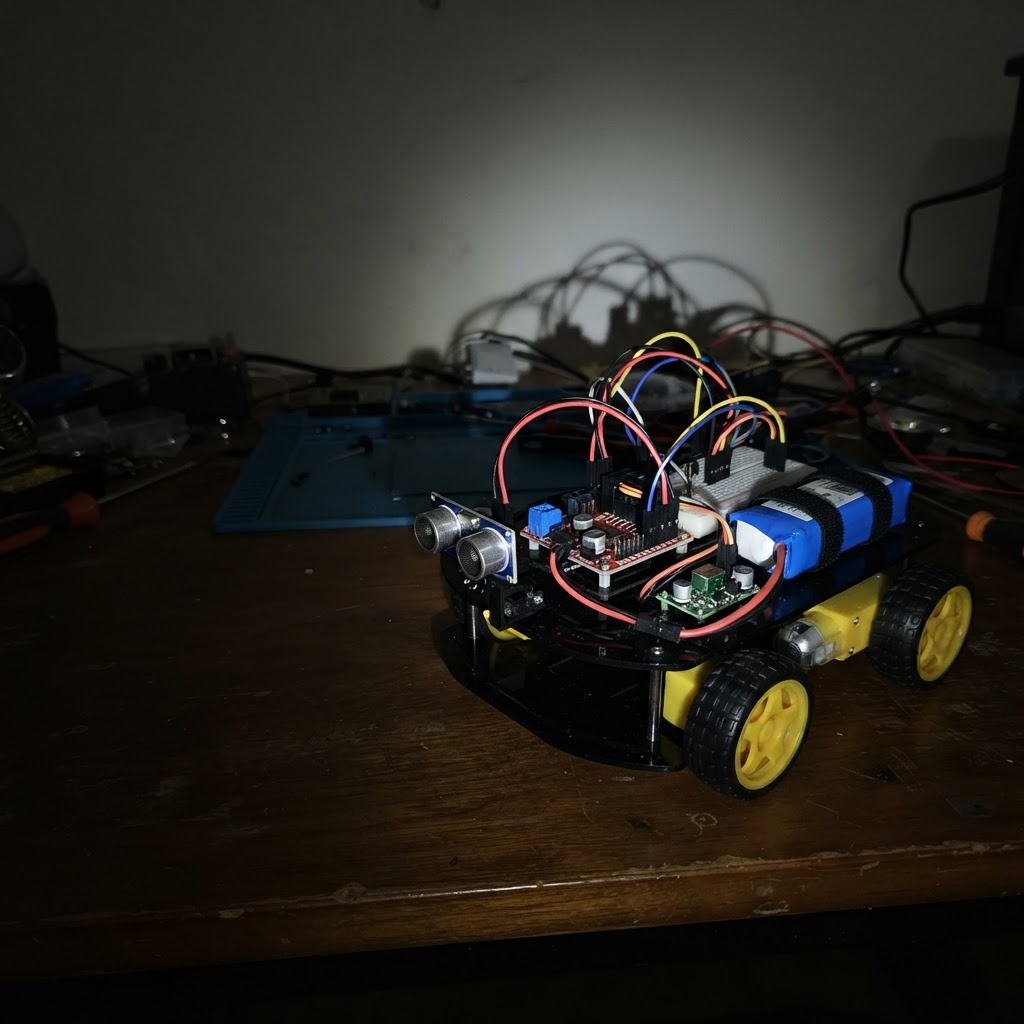
This obstacle-avoiding rover uses a Raspberry Pi Pico to autonomously navigate around obstacles using an HC-SR04 ultrasonic sensor. The rover drives forward at a set speed, continuously scanning for obstacles ahead, and when something gets too close, it stops, backs up, turns, and resumes its journey.
The guide provides a complete wiring diagram, parts list, and ready-to-upload firmware. Assembly covers mounting the motors and L298N motor driver to the chassis, wiring the dual DC motors for independent left and right control, setting up the 2S LiPo battery with regulated 5V power for the Pico and sensor, protecting the HC-SR04 signal lines with a level shifter, and performing a safe first power-on test.
Wiring diagram

Gather all the parts
Assemble it in 6 steps
1. Prepare the chassis and motor driver
Mount the Pico, L298N module, battery holder, and the two motors securely. Keep the motor wires away from the ultrasonic sensor face. Remove the ENA and ENB jumpers from the L298N so the Pico can control motor speed with PWM.
- Fit a caster wheel at the front or rear of the two-wheel chassis.
- Do not power the circuit while making or changing connections.
- The L298N gets warm during use; leave airflow around its heatsink.
- Confirm each motor's stall current is within the L298N module's real thermal capability.
2. Wire both motors to the L298N
Connect the left motor's two leads to OUT1 and OUT2. Connect the right motor's two leads to OUT3 and OUT4. If a motor runs opposite to the intended direction during testing, swap only that motor's two output leads.
- Use short, secure motor wires to reduce electrical noise.
- Never connect a motor directly to a Pico GPIO pin.
3. Make the battery and regulated 5 V power wiring
Connect battery BAT+ to the L298N VS motor-supply input and to buck VIN. Connect battery BAT− to L298N GND and buck GND. Before connecting loads, adjust and measure the buck VOUT as exactly 5.0 V. Then connect buck VOUT to Pico VSYS and HC-SR04 VCC; connect their grounds to the same common ground.
- Add an inline power switch or unplug the battery when the rover is not in use.
- The Pico is fed at VSYS with regulated 5 V, not through a GPIO pin.
- Verify the buck output with a multimeter before connecting the Pico or sensor: more than 5.5 V can damage them.
- All grounds—battery, buck, L298N, Pico, and HC-SR04—must be connected together.
- Use a proper 2S LiPo charger/balancer appropriate for your battery; do not charge it through this circuit.
4. Wire Pico control signals to the L298N
Connect Pico GP2 to IN1, GP3 to IN2, GP4 to ENA, GP6 to IN3, GP7 to IN4, and GP8 to ENB on the L298N. Keep ENA and ENB jumpers removed.
- Use the Pico's labeled GP pin numbers, not physical header-pin positions.
- The L298N inputs accept the Pico's 3.3 V logic levels.
- Do not connect the L298N 5 V pin to a Pico GPIO.
5. Wire and protect the HC-SR04 signal
Connect HC-SR04 TRIG to Pico GP10, VCC to regulated 5 V, and GND to common ground. Create a voltage divider for ECHO: HC-SR04 ECHO → 10 kΩ resistor → junction → Pico GP11; from that same junction connect a 20 kΩ resistor to common ground. This reduces the 5 V ECHO signal to about 3.3 V.
- Mount the two ultrasonic transducers facing straight forward and clear of the chassis.
- Keep the divider junction insulated so it cannot short to adjacent wiring.
- Never connect a standard 5 V HC-SR04 ECHO pin directly to Pico GP11; Pico GPIO pins are 3.3 V-only.
6. Perform a safe first power-on
Lift the drive wheels off the ground, connect the battery, and use Schematik's Deploy button to flash the rover firmware. The rover drives forward when it sees clear space. At 25 cm or closer it stops, reverses briefly, then pivots right before continuing.
- If the rover drives backward instead of forward, swap both leads of both motors or reverse the relevant direction logic.
- If it pivots the wrong way, swap one motor's leads or change the turn direction in firmware.
- Keep hands, hair, and loose wires away from the wheels during powered testing.
- Disconnect battery power before altering any wiring.
Review all connections
1. Connections between "buck" and "Raspberry Pi Pico"
2. Connections between "driver" and "Raspberry Pi Pico"
3. Connections between "left_motor" and "Raspberry Pi Pico"
4. Connections between "right_motor" and "Raspberry Pi Pico"
5. Connections between "ultrasonic" and "Raspberry Pi Pico"
6. Connections between "battery" and "Raspberry Pi Pico"
7. Connections between "power_distribution" and "Raspberry Pi Pico"
8. Connections between "level_shifter" and "Raspberry Pi Pico"
Deploy the firmware
#include <Arduino.h>
// HC-SR04 signal paths pass through a 3.3V/5V level shifter.

// Forward declarations
void motor(int a, int b, int en, int value);
void drive(int left, int right);
unsigned int distanceCm();

const int LEFT_IN1 = 2, LEFT_IN2 = 3, LEFT_EN = 4;
const int RIGHT_IN1 = 6, RIGHT_IN2 = 7, RIGHT_EN = 8;
const int TRIG_PIN = 10, ECHO_PIN = 11;
const int CRUISE_SPEED = 190, TURN_SPEED = 175;
const unsigned int OBSTACLE_CM = 25;

void motor(int a, int b, int en, int value) {
  value = constrain(value, -255, 255);
  digitalWrite(a, value > 0 ? HIGH : LOW);
  digitalWrite(b, value < 0 ? HIGH : LOW);
  analogWrite(en, abs(value));
}
void drive(int left, int right) { motor(LEFT_IN1, LEFT_IN2, LEFT_EN, left); motor(RIGHT_IN1, RIGHT_IN2, RIGHT_EN, right); }
unsigned int distanceCm() {
  digitalWrite(TRIG_PIN, LOW); delayMicroseconds(3);
  digitalWrite(TRIG_PIN, HIGH); delayMicroseconds(10); digitalWrite(TRIG_PIN, LOW);
  unsigned long us = pulseIn(ECHO_PIN, HIGH, 30000UL);
  return us ? us / 58UL : 0;
}
void setup() {
  pinMode(LEFT_IN1, OUTPUT); pinMode(LEFT_IN2, OUTPUT); pinMode(LEFT_EN, OUTPUT);
  pinMode(RIGHT_IN1, OUTPUT); pinMode(RIGHT_IN2, OUTPUT); pinMode(RIGHT_EN, OUTPUT);
  pinMode(TRIG_PIN, OUTPUT); pinMode(ECHO_PIN, INPUT);
  drive(0, 0);
}
void loop() {
  unsigned int cm = distanceCm();
  if (cm && cm <= OBSTACLE_CM) {
    drive(0, 0); delay(120); drive(-CRUISE_SPEED, -CRUISE_SPEED); delay(300);
    drive(TURN_SPEED, -TURN_SPEED); delay(480); drive(0, 0); delay(80);
  } else drive(CRUISE_SPEED, CRUISE_SPEED);
  delay(90);
}
Remix this project
Make it yours in one click
Open a full copy of this project in your own Schematik workspace — diagram, code, parts, and assembly steps included. Swap the sensor, add features, or redesign the whole thing with AI. The author's original stays untouched.
Related projects
Fridge Scale Smart Clip
Raspberry Pi Pico · September 14, 2026Phillip Knopp
Tiny Robot AI Assistant
Raspberry Pi Pico · September 13, 2026Shaikh Tajmul haque
Tiny Spider Robot
Raspberry Pi Pico · September 13, 2026Shaikh Tajmul haque