Community project
Parkinson’s Tremor Detection Pen
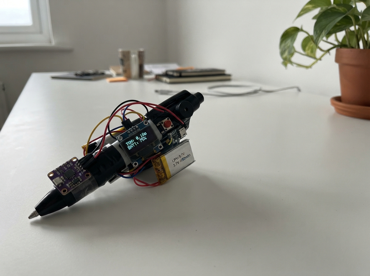
This guide builds a portable tremor detection pen that monitors hand movement patterns to support Parkinson's disease assessment. The device uses a 6-axis motion sensor to capture acceleration and rotation data, a force-sensing resistor to measure grip pressure, and an OLED display to show real-time readings. The ESP32 microcontroller processes sensor data and stores measurements for later analysis.
Readers will receive a complete parts list, wiring diagram showing all sensor and control connections, step-by-step assembly instructions, and the full Arduino firmware needed to run the device. The guide covers building the battery power chain with charging protection, calibrating the motion sensor, and testing the display and buttons before first use.
Wiring diagram

Gather all the parts
Assemble it in 6 steps
1. Place the electronics safely
Keep the ESP32, charger, boost module, and battery outside the narrow writing grip at first. Mount the MPU6050 firmly near the pen tip and tape the round sensing area of the FSR402 where the user naturally grips the pen. A loose motion sensor measures casing movement instead of the writing motion.
- Use short, flexible wires along the pen body so they do not pull on the sensor while writing.
- The OLED, two buttons, and buzzer can sit on a small handle enclosure or test board.
- Do not puncture, bend sharply, crush, or solder directly onto the LiPo battery — damage can cause it to overheat or catch fire.
2. Make the 3.3 V sensor connections
With the ESP32 unplugged, connect MPU6050 VIN to ESP32 3V3 (power), MPU6050 GND to ESP32 GND (ground), MPU6050 SDA to GPIO21 (data), and MPU6050 SCL to GPIO22 (clock). Connect OLED VCC to ESP32 3V3 (power), OLED GND to ESP32 GND (ground), OLED SDA to GPIO21 (data), and OLED SCL to GPIO22 (clock).
- Both the screen and motion sensor share the same two data wires; this is normal.
- Keep the sensor and OLED on 3.3 V so their data wires remain safe for the ESP32.
- Make sure VCC and GND are not swapped — swapped power can damage the screen or motion sensor.
3. Wire the grip-pressure sensor
Connect FSR402 Pin 1 to ESP32 3V3 (power). Connect FSR402 Pin 2 to GPIO34 (pressure signal) and also to one lead of the 10 kΩ resistor (signal junction). Connect the resistor's other lead to ESP32 GND (ground).
- GPIO34 is input-only, which is exactly what this pressure measurement needs.
- The FSR's flexible tail is delicate; reinforce it with tape or a connector so repeated writing does not tear it.
- Do not connect the FSR signal to 5 V — the ESP32 input can be damaged by voltages above 3.3 V.
4. Wire the controls and sounder
Connect the GND pin of the record/start button to ESP32 GND (ground) and its SIGNAL pin to GPIO25 (signal). Connect the GND pin of the event/stop button to ESP32 GND (ground) and its SIGNAL pin to GPIO26 (signal). Connect buzzer GND to ESP32 GND (ground) and buzzer SIGNAL to GPIO27 (sound signal).
- The firmware treats a quick tap as exactly one press: GPIO25 starts or stops a recording and GPIO26 adds a user-mark event to the USB data stream.
- If the buzzer has a + marking, connect that marked pin to GPIO27 and its other pin to GND.
- Do not use a large high-current buzzer directly from GPIO27; use only a small logic-level piezo/active buzzer like the listed part.
5. Build the protected battery power chain
Connect battery +V to TP4056 B+ (battery positive) and battery GND to TP4056 B- (battery negative). Connect TP4056 OUT+ to boost-module IN+ (protected battery power) and TP4056 OUT- to boost-module IN- (protected ground). Before connecting the ESP32, power the boost module from the battery and adjust it with a meter until OUT+ to OUT- reads exactly 5.0 V. Then connect boost OUT+ to ESP32 VIN (5 V power) and boost OUT- to ESP32 GND (ground). Connect the TP4056 IN+ and IN- only to its own 5 V USB charging cable (charging power).
- Use a TP4056 module with B+/B-/OUT+/OUT- pads, because the OUT pads provide the module's protection path.
- The ESP32's normal USB connector remains the data link to the Python application.
- Never connect the TP4056 charging input to the ESP32 3V3 pin or directly to the battery.
- Set the boost output to exactly 5.0 V before connecting VIN — a higher setting can damage the ESP32.
- Do not attempt to charge a non-rechargeable battery or an unprotected bare cell.
6. Connect the data cable and check the startup screen
Plug the ESP32's normal USB data cable into the computer running the Python CNN application. This cable provides USB serial communication at 115200 baud. After flashing, the screen should say MPU ready; press GPIO25's button to begin sending 50 motion-and-grip JSON readings each second, and press GPIO26's button to add a user-mark line.
- The Python application should read one JSON object per line and use only sample lines that contain ax, ay, az, gx, gy, gz, and fsr.
- This device collects movement and grip features for research or screening support; its output must not be used alone to diagnose Parkinson's disease.
- Do not connect the computer USB cable and the TP4056 charging cable to an unverified shared power setup until you have checked that all grounds and voltages are correct.
Review all connections
1. Connections between "mpu6050_1" and "ESP32"
2. Connections between "oled_1" and "ESP32"
3. Connections between "start_button" and "ESP32"
4. Connections between "mark_button" and "ESP32"
5. Connections between "buzzer_1" and "ESP32"
6. Connections between "fsr_1" and "ESP32"
7. Connections between "fsr_resistor" and "ESP32"
8. Connections between "tp4056_1" and "ESP32"
9. Connections between "battery_1" and "ESP32"
10. Connections between "boost_1" and "ESP32"
Deploy the firmware
#include <Arduino.h>
#include <Wire.h>
#include <Adafruit_MPU6050.h>
#include <Adafruit_Sensor.h>
#include <Adafruit_GFX.h>
#include <Adafruit_SSD1306.h>

constexpr int I2C_SDA_PIN = 21;
constexpr int I2C_SCL_PIN = 22;
constexpr int START_BUTTON_PIN = 25;
constexpr int MARK_BUTTON_PIN = 26;
constexpr int BUZZER_PIN = 27;
constexpr int FSR_PIN = 34;
constexpr uint8_t OLED_ADDRESS = 0x3C;
constexpr int SCREEN_WIDTH = 128;
constexpr int SCREEN_HEIGHT = 64;
constexpr uint32_t SAMPLE_INTERVAL_MS = 20;
constexpr uint32_t DISPLAY_INTERVAL_MS = 250;
constexpr uint32_t DEBOUNCE_MS = 35;

Adafruit_MPU6050 mpu;
Adafruit_SSD1306 display(SCREEN_WIDTH, SCREEN_HEIGHT, &Wire, -1);

bool recording = false;
bool mpuReady = false;
float ax = 0.0f, ay = 0.0f, az = 0.0f, gx = 0.0f, gy = 0.0f, gz = 0.0f;
int fsrRaw = 0;
uint32_t lastSampleMs = 0;
uint32_t lastDisplayMs = 0;
uint32_t sampleNumber = 0;

bool lastStartReading = HIGH;
bool stableStartState = HIGH;
uint32_t startChangedMs = 0;
bool lastMarkReading = HIGH;
bool stableMarkState = HIGH;
uint32_t markChangedMs = 0;

void beep(uint16_t frequency, uint16_t durationMs) {
  ledcWriteTone(BUZZER_PIN, frequency);
  delay(durationMs);
  ledcWriteTone(BUZZER_PIN, 0);
}

void drawStatus() {
  display.clearDisplay();
  display.setTextColor(SSD1306_WHITE);
  display.setTextSize(1);
  display.setCursor(0, 0);
  display.println("Parkinson's pen");
  display.drawLine(0, 10, SCREEN_WIDTH - 1, 10, SSD1306_WHITE);
  display.setCursor(0, 16);
  display.print("MPU: ");
  display.println(mpuReady ? "ready" : "not found");
  display.setCursor(0, 28);
  display.print("Grip: ");
  display.println(fsrRaw);
  display.setCursor(0, 40);
  display.print("USB CNN: JSON lines");
  display.setCursor(0, 52);
  display.print(recording ? "REC  #" : "READY");
  if (recording) display.print(sampleNumber);
  display.display();
}

void sendHeader() {
  Serial.println("{\"type\":\"smart_pen\",\"format\":\"jsonl\",\"sample_hz\":50,\"units\":{\"accel\":\"m_s2\",\"gyro\":\"rad_s\"},\"fields\":[\"t_ms\",\"ax\",\"ay\",\"az\",\"gx\",\"gy\",\"gz\",\"fsr\"]}");
}

void sendSample(uint32_t now) {
  Serial.print("{\"t_ms\":"); Serial.print(now);
  Serial.print(",\"ax\":"); Serial.print(ax, 5);
  Serial.print(",\"ay\":"); Serial.print(ay, 5);
  Serial.print(",\"az\":"); Serial.print(az, 5);
  Serial.print(",\"gx\":"); Serial.print(gx, 5);
  Serial.print(",\"gy\":"); Serial.print(gy, 5);
  Serial.print(",\"gz\":"); Serial.print(gz, 5);
  Serial.print(",\"fsr\":"); Serial.print(fsrRaw);
  Serial.println("}");
}

bool pressedEvent(int pin, bool &lastReading, bool &stableState, uint32_t &changedMs, uint32_t now) {
  const bool reading = digitalRead(pin);
  if (reading != lastReading) changedMs = now;
  if ((now - changedMs) >= DEBOUNCE_MS && reading != stableState) {
    stableState = reading;
    lastReading = reading;
    return stableState == LOW;
  }
  lastReading = reading;
  return false;
}

void setup() {
  Serial.begin(115200);
  analogReadResolution(12);
  pinMode(START_BUTTON_PIN, INPUT_PULLUP);
  pinMode(MARK_BUTTON_PIN, INPUT_PULLUP);
  ledcAttach(BUZZER_PIN, 2000, 8);
  ledcWriteTone(BUZZER_PIN, 0);

  Wire.begin(I2C_SDA_PIN, I2C_SCL_PIN);
  mpuReady = mpu.begin(0x68, &Wire);
  if (mpuReady) {
    mpu.setAccelerometerRange(MPU6050_RANGE_8_G);
    mpu.setGyroRange(MPU6050_RANGE_500_DEG);
    mpu.setFilterBandwidth(MPU6050_BAND_21_HZ);
  }

  if (!display.begin(SSD1306_SWITCHCAPVCC, OLED_ADDRESS)) {
    Serial.println("{\"type\":\"error\",\"message\":\"OLED not found at 0x3C\"}");
  }
  if (mpuReady) {
    Serial.println("{\"type\":\"status\",\"message\":\"MPU6050 ready\"}");
    beep(2200, 70);
  } else {
    Serial.println("{\"type\":\"error\",\"message\":\"MPU6050 not found at 0x68\"}");
    beep(450, 250);
  }
  sendHeader();
  drawStatus();
}

void loop() {
  const uint32_t now = millis();
  if (pressedEvent(START_BUTTON_PIN, lastStartReading, stableStartState, startChangedMs, now)) {
    recording = !recording;
    if (recording) {
      sampleNumber = 0;
      Serial.println("{\"type\":\"recording\",\"state\":\"started\"}");
      beep(1800, 70);
    } else {
      Serial.println("{\"type\":\"recording\",\"state\":\"stopped\"}");
      beep(900, 120);
    }
    drawStatus();
  }
  if (pressedEvent(MARK_BUTTON_PIN, lastMarkReading, stableMarkState, markChangedMs, now)) {
    Serial.print("{\"type\":\"event\",\"t_ms\":");
    Serial.print(now);
    Serial.println(",\"name\":\"user_mark\"}");
    beep(2600, 45);
  }
  if (recording && now - lastSampleMs >= SAMPLE_INTERVAL_MS) {
    lastSampleMs = now;
    fsrRaw = analogRead(FSR_PIN);
    if (mpuReady) {
      sensors_event_t acceleration, gyroscope, temperature;
      mpu.getEvent(&acceleration, &gyroscope, &temperature);
      ax = acceleration.acceleration.x;
      ay = acceleration.acceleration.y;
      az = acceleration.acceleration.z;
      gx = gyroscope.gyro.x;
      gy = gyroscope.gyro.y;
      gz = gyroscope.gyro.z;
    } else {
      ax = ay = az = gx = gy = gz = 0.0f;
    }
    sendSample(now);
    ++sampleNumber;
  }
  if (now - lastDisplayMs >= DISPLAY_INTERVAL_MS) {
    lastDisplayMs = now;
    if (!recording) fsrRaw = analogRead(FSR_PIN);
    drawStatus();
  }
}
Remix this project
Make it yours in one click
Open a full copy of this project in your own Schematik workspace — diagram, code, parts, and assembly steps included. Swap the sensor, add features, or redesign the whole thing with AI. The author's original stays untouched.