Community project
Portable AI Desk Companion
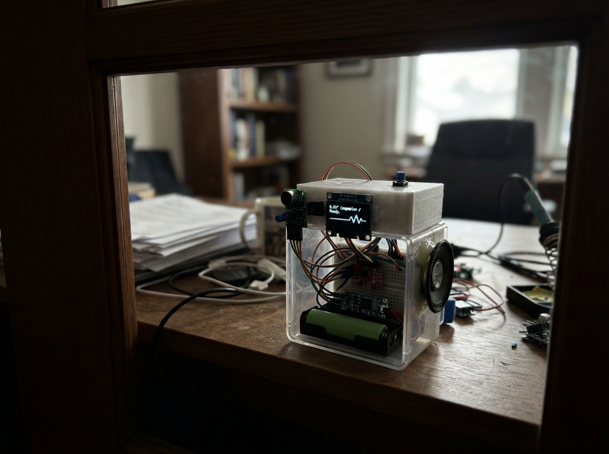
This portable AI desk companion brings a responsive interface to your workspace, combining an ESP32 microcontroller with a compact OLED display, sound sensor, and speaker amplifier. The device runs on a single 18650 Li-ion cell boosted to 5V, making it truly mobile for desk-to-desk use or travel.
This guide provides a complete wiring diagram, parts list, and step-by-step assembly instructions to build your own unit. The included firmware handles four push-button controls for recording, muting, snoozing, and dismissing alerts, while the OLED screen displays real-time feedback and the sound sensor captures audio input for processing.
Wiring diagram

Gather all the parts
Assemble it in 6 steps
1. Set the boost module to 5 V
Before connecting the ESP32, insert the 18650 into holder_1 and connect holder_1 BAT+ to boost_1 VIN+ (battery power) and holder_1 BAT- to boost_1 VIN- (battery return). Use a multimeter across boost_1 VOUT+ and VOUT- and adjust the tiny screw until it reads 5.0 V.
- Do this adjustment with the ESP32 disconnected so an incorrectly adjusted module cannot damage it.
- Do not connect the cell straight to the ESP32 VIN pin: the voltage changes as the cell empties and will not run the 5 V VIN input reliably.
- Do not short the battery contacts; a Li-ion cell can become dangerously hot.
2. Make the 5 V and ground rails
Connect boost_1 VOUT+ to the ESP32 VIN pin (regulated 5 V power) and to amp_1 VCC (amplifier power). Connect boost_1 VOUT- to an ESP32 GND pin (ground), then connect amp_1 GND to the same ground rail (ground).
- All modules need the same ground connection or their signal wires cannot work correctly.
- Make sure VOUT+ is 5.0 V before connecting it to VIN or the amplifier — a higher setting can damage them.
3. Wire the display and microphone
Connect oled_1 VCC to ESP32 3V3 (power), oled_1 GND to GND (ground), oled_1 SDA to GPIO21 (data), and oled_1 SCL to GPIO22 (clock). Connect mic_1 VCC to ESP32 3V3 (power), mic_1 GND to GND (ground), and mic_1 AO to GPIO34 (sound-level signal). Leave mic_1 DO unconnected.
- The screen normally has its pin names printed beside the four header pins. GPIO34 is input-only, which is exactly what the microphone needs.
- Power the KY-038 from 3.3 V, not 5 V — its AO pin can otherwise rise above the safe ESP32 input voltage.
4. Wire the speaker amplifier
Connect ESP32 GPIO25 to amp_left_resistor P1 (audio signal). Join amp_right_resistor P1 to that same GPIO25-to-amp_left_resistor P1 junction (shared audio signal). Connect amp_left_resistor P2 to amp_1 L_IN (left audio input) and amp_right_resistor P2 to amp_1 R_IN (right audio input). Connect amp_1 L+ to speaker_1 + (speaker drive) and amp_1 L- to speaker_1 - (speaker drive). Leave amp_1 R+ and R- unconnected.
- The same mono tone is fed into both amplifier inputs, but only the left speaker output is used.
- The PAM8403 speaker outputs are a pair: connect the speaker only between L+ and L-.
- Never connect speaker_1 - to GND — the PAM8403 output is not a ground-referenced speaker output and this can damage the amplifier.
5. Wire the four button controls
For push-to-talk, connect ptt_button GND to GND (ground), join ptt_button SIGNAL to ptt_pulldown P1, connect that shared junction to GPIO16 (button signal), and connect ptt_pulldown P2 to GND (keeps the signal low). Repeat the same pattern: snooze_button SIGNAL and snooze_pulldown P1 to GPIO17; dismiss_button SIGNAL and dismiss_pulldown P1 to GPIO18; mute_button SIGNAL and mute_pulldown P1 to GPIO19. Connect every button GND pin and every pull-down resistor P2 pin to GND.
- On a 4-leg tactile switch, the two legs on each same side are already connected. Put the button across the center gap of a breadboard so pressing it connects the two sides.
- Each 10 kΩ resistor has no direction; either end may go to ground.
- Do not connect a button signal wire directly to 3.3 V without its pull-down resistor arrangement — an incorrect connection can force a pin to conflicting voltages.
6. Check the device before closing it
Recheck that every GND connection reaches the same ground rail, that the OLED and microphone use 3.3 V, and that only the ESP32 VIN and PAM8403 VCC receive the regulated 5 V rail. Fit the parts into the enclosure only after these connections are correct.
- Keep the microphone physically away from the speaker; this reduces squealing and false sound readings.
- Remove the 18650 before moving wires. Make sure VCC and GND are not swapped — swapped power can damage the screen, microphone, or amplifier.
Review all connections
1. Connections between "oled_1" and "ESP32"
2. Connections between "mic_1" and "ESP32"
3. Connections between "amp_1" and "ESP32"
4. Connections between "amp_left_resistor" and "ESP32"
5. Connections between "amp_right_resistor" and "ESP32"
6. Connections between "ptt_button" and "ESP32"
7. Connections between "ptt_pulldown" and "ESP32"
8. Connections between "snooze_button" and "ESP32"
9. Connections between "snooze_pulldown" and "ESP32"
10. Connections between "dismiss_button" and "ESP32"
11. Connections between "dismiss_pulldown" and "ESP32"
12. Connections between "mute_button" and "ESP32"
13. Connections between "mute_pulldown" and "ESP32"
14. Connections between "battery_1" and "ESP32"
15. Connections between "holder_1" and "ESP32"
16. Connections between "boost_1" and "ESP32"
Deploy the firmware
#include <Arduino.h>
#include <Wire.h>
#include <Adafruit_GFX.h>
#include <Adafruit_SSD1306.h>


// Hoisted type definitions
struct Button {
  uint8_t pin;
  bool stableState;
  bool lastReading;
  unsigned long changedAt;
};


// Forward declarations
bool wasPressed(Button &button);
void drawFace();
void playTone(uint16_t frequency, uint16_t durationMs);

constexpr int OLED_SDA = 21;
constexpr int OLED_SCL = 22;
constexpr int MIC_PIN = 34;
constexpr int AUDIO_PIN = 25;
constexpr int PTT_PIN = 16;
constexpr int SNOOZE_PIN = 17;
constexpr int DISMISS_PIN = 18;
constexpr int MUTE_PIN = 19;

constexpr uint8_t SCREEN_WIDTH = 128;
constexpr uint8_t SCREEN_HEIGHT = 64;
constexpr uint8_t OLED_ADDRESS = 0x3C;
constexpr uint8_t AUDIO_CHANNEL = 0;
constexpr uint16_t AUDIO_PWM_HZ = 2000;
constexpr uint8_t AUDIO_RESOLUTION = 8;
constexpr uint16_t DEBOUNCE_MS = 35;
constexpr uint16_t SAMPLE_INTERVAL_MS = 100;

Adafruit_SSD1306 display(SCREEN_WIDTH, SCREEN_HEIGHT, &Wire, -1);

bool muted = false;
bool snoozed = false;
bool dismissed = false;
bool recording = false;
int micLevel = 0;
unsigned long lastSampleMs = 0;


Button pttButton{PTT_PIN, false, false, 0};
Button snoozeButton{SNOOZE_PIN, false, false, 0};
Button dismissButton{DISMISS_PIN, false, false, 0};
Button muteButton{MUTE_PIN, false, false, 0};

bool wasPressed(Button &button) {
  const bool reading = digitalRead(button.pin) == HIGH;
  if (reading != button.lastReading) {
    button.changedAt = millis();
    button.lastReading = reading;
  }
  if ((millis() - button.changedAt) > DEBOUNCE_MS && reading != button.stableState) {
    button.stableState = reading;
    return button.stableState;
  }
  return false;
}

void drawFace() {
  display.clearDisplay();
  display.drawCircle(64, 34, 25, SSD1306_WHITE);
  display.fillCircle(54, 29, 3, SSD1306_WHITE);
  display.fillCircle(74, 29, 3, SSD1306_WHITE);

  if (snoozed) {
    display.drawLine(53, 44, 75, 44, SSD1306_WHITE);
    display.setTextSize(1);
    display.setCursor(4, 2);
    display.print("SNOOZED");
  } else if (dismissed) {
    display.drawLine(54, 47, 74, 42, SSD1306_WHITE);
    display.setTextSize(1);
    display.setCursor(4, 2);
    display.print("DISMISSED");
  } else if (recording) {
    display.drawCircle(64, 46, 7, SSD1306_WHITE);
    display.setTextSize(1);
    display.setCursor(4, 2);
    display.print("LISTENING");
  } else {
    display.drawCircle(64, 42, 10, SSD1306_WHITE);
    display.fillRect(54, 37, 21, 5, SSD1306_BLACK);
    display.setTextSize(1);
    display.setCursor(4, 2);
    display.print(muted ? "MUTED" : "READY");
  }

  display.setTextSize(1);
  display.setCursor(4, 54);
  display.print("Mic: ");
  display.print(micLevel);
  display.display();
}

void playTone(uint16_t frequency, uint16_t durationMs) {
  if (muted) return;
  ledcWriteTone(AUDIO_CHANNEL, frequency);
  delay(durationMs);
  ledcWriteTone(AUDIO_CHANNEL, 0);
}

void setup() {
  Serial.begin(115200);

  pinMode(PTT_PIN, INPUT);
  pinMode(SNOOZE_PIN, INPUT);
  pinMode(DISMISS_PIN, INPUT);
  pinMode(MUTE_PIN, INPUT);
  analogReadResolution(12);

  ledcSetup(AUDIO_CHANNEL, AUDIO_PWM_HZ, AUDIO_RESOLUTION);
  ledcAttachPin(AUDIO_PIN, AUDIO_CHANNEL);
  ledcWriteTone(AUDIO_CHANNEL, 0);

  Wire.begin(OLED_SDA, OLED_SCL);
  if (!display.begin(SSD1306_SWITCHCAPVCC, OLED_ADDRESS)) {
    Serial.println("SSD1306 display was not found. Check VCC, GND, SDA, and SCL.");
    while (true) delay(1000);
  }

  drawFace();
  playTone(880, 80);
}

void loop() {
  if (wasPressed(snoozeButton)) {
    snoozed = !snoozed;
    dismissed = false;
    playTone(523, 100);
    drawFace();
  }

  if (wasPressed(dismissButton)) {
    dismissed = true;
    snoozed = false;
    playTone(392, 100);
    drawFace();
  }

  if (wasPressed(muteButton)) {
    muted = !muted;
    if (!muted) playTone(660, 80);
    drawFace();
  }

  const bool pttNow = digitalRead(PTT_PIN) == HIGH;
  if (pttNow != recording) {
    recording = pttNow;
    if (recording) {
      snoozed = false;
      dismissed = false;
      playTone(740, 60);
    } else {
      playTone(440, 80);
    }
    drawFace();
  }

  if (recording && millis() - lastSampleMs >= SAMPLE_INTERVAL_MS) {
    lastSampleMs = millis();
    micLevel = analogRead(MIC_PIN);
    Serial.print("Microphone level: ");
    Serial.println(micLevel);
    drawFace();
  }
}
Remix this project
Make it yours in one click
Open a full copy of this project in your own Schematik workspace — diagram, code, parts, and assembly steps included. Swap the sensor, add features, or redesign the whole thing with AI. The author's original stays untouched.
Related projects

Create A Complete Electrical Schematic Esp32 Sma
ESP32 · September 17, 2026Ayansh Agrawal
ESP32 Kare Ekran Projeleri
ESP32 · September 16, 2026Seref Ai
Component Qty --------------------------- ------
ESP32 · September 16, 2026Yathartha Chakrawal