Community project
Portable Bluetooth Hotkey Button
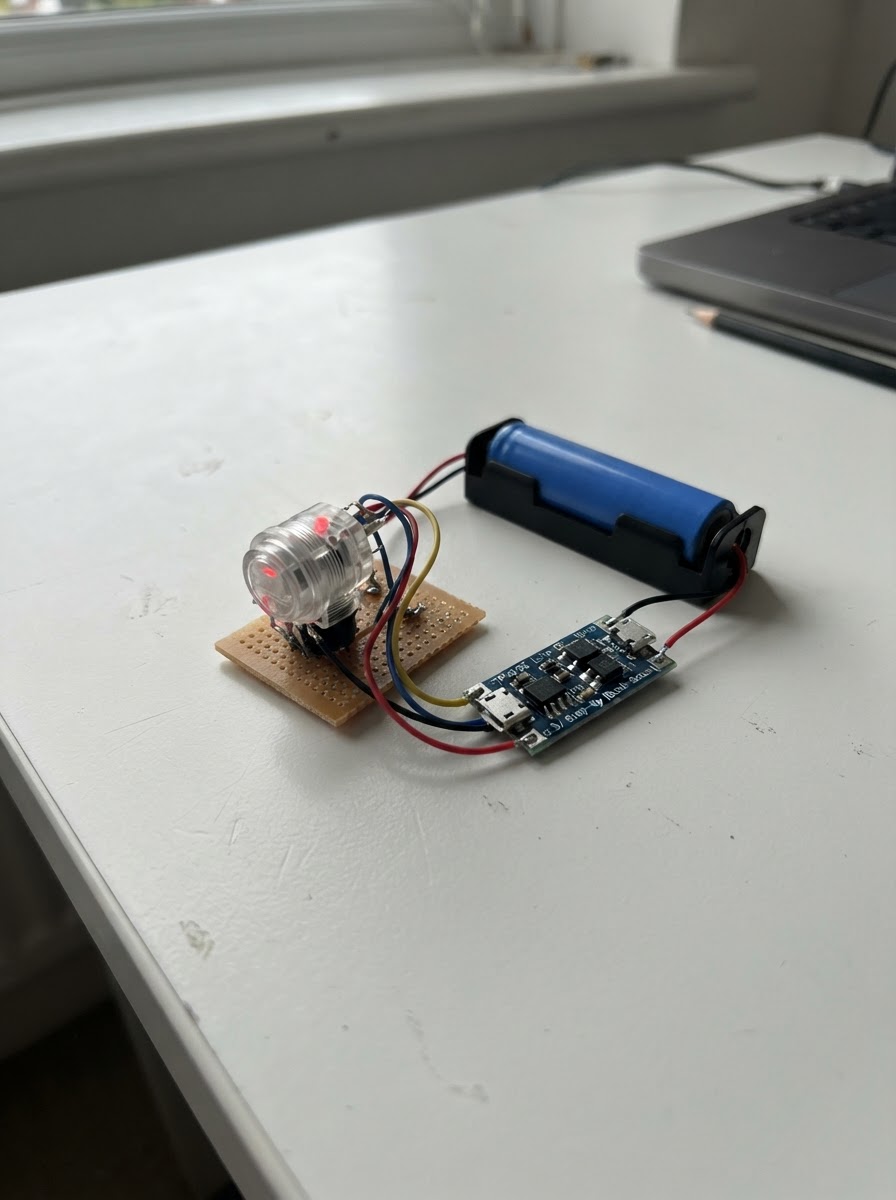
This project builds a portable Bluetooth hotkey button that sends a customizable keyboard shortcut (Ctrl+Alt+F9 by default) to any connected device. The single arcade button is housed in a compact enclosure and powered by a protected 18650 battery, making it ideal for triggering emergency functions, application shortcuts, or accessibility commands from anywhere within Bluetooth range.
The guide provides a complete wiring diagram, parts list, and step-by-step assembly instructions for integrating the ESP32 microcontroller, charging circuit, and power regulation. Customizable firmware handles debouncing, Bluetooth connectivity status indication via the button's LED, and reliable hotkey transmission with connection checking.
Wiring diagram

Gather all the parts
Assemble it in 4 steps
1. Prepare the enclosure and button
Make the mounting hole required by your chosen large red normally-open arcade button (24 mm for the selected catalog style). Fit the button and tighten its retaining nut; keep the switch terminals and LED terminals identifiable.
- Choose a red button whose LED section is rated for 3.3 V or has an internal resistor.
- Use an enclosure that cannot let the battery terminals or power-board solder joints touch metal.
- Do not use a latching on/off switch as the hotkey button; it must be a momentary, normally-open switch.
2. Wire the button
Connect button SW1 to ESP32 GPIO27 and SW2 to an ESP32 GND pin. Connect LED+ to GPIO13 and LED- to ESP32 GND. The firmware uses GPIO27’s internal pull-up, so no extra switch resistor is needed.
- Keep these wires short and strain-relieved.
- GPIO13 turns the button light on only after the PC has connected over Bluetooth.
- Do not connect the switch contact to 3.3 V; it is wired between GPIO27 and ground.
3. Build the protected battery and regulator chain
Install a protected 18650 cell in its holder. Connect battery +V to charger B+ and battery GND to charger B-. Connect charger OUT+ to regulator VIN and charger OUT- to regulator GND. Set the regulator output to exactly 3.3 V with a multimeter before connecting the ESP32.
- Use the charger module’s protected OUT+/OUT- terminals for the load, not B+/B-.
- A 2500 mAh cell is estimated at roughly 16 hours of active use; actual time depends heavily on Bluetooth connection activity and regulator efficiency.
- Never short, puncture, reverse, or charge an 18650 cell without protection.
- Do not connect the 4.2 V battery/charger output directly to the ESP32 3V3 pin.
- Use only the TP4056 module’s 5 V USB input for charging.
4. Power the ESP32
Connect regulator VOUT to the ESP32 3V3 pin. Ensure regulator GND, charger OUT-, and the ESP32 GND pins are all common ground. Mount and insulate the boards so they cannot short against the enclosure or battery holder.
- Verify 3.3 V again between ESP32 3V3 and GND before installing the ESP32.
- Use a separate accessible USB opening for the TP4056 charging connector.
- Do not feed the regulator’s 3.3 V output into ESP32 VIN/5V.
- Disconnect battery power before changing wiring.
Review all connections
1. Connections between "button_1" and "ESP32"
2. Connections between "battery_1" and "ESP32"
3. Connections between "charger_1" and "ESP32"
4. Connections between "regulator_1" and "ESP32"
Deploy the firmware
#include <Arduino.h>
#include <BleKeyboard.h>


// Forward declarations
void sendHotkey();

constexpr uint8_t BUTTON_PIN = 27;
constexpr uint8_t BUTTON_LED_PIN = 13;
constexpr uint32_t DEBOUNCE_MS = 35;
constexpr uint32_t KEY_HOLD_MS = 40;

BleKeyboard bleKeyboard("Emergency Hotkey Button", "Schematik", 100);

bool rawLast = HIGH;
bool stableState = HIGH;
uint32_t rawChangedAt = 0;

void sendHotkey() {
  if (!bleKeyboard.isConnected()) {
    return;
  }

  bleKeyboard.press(KEY_LEFT_CTRL);
  bleKeyboard.press(KEY_LEFT_ALT);
  bleKeyboard.press(KEY_F9);
  delay(KEY_HOLD_MS);
  bleKeyboard.releaseAll();
}

void setup() {
  pinMode(BUTTON_PIN, INPUT_PULLUP);
  pinMode(BUTTON_LED_PIN, OUTPUT);
  digitalWrite(BUTTON_LED_PIN, LOW);
  bleKeyboard.begin();
}

void loop() {
  const bool connected = bleKeyboard.isConnected();
  digitalWrite(BUTTON_LED_PIN, connected ? HIGH : LOW);

  const bool rawNow = digitalRead(BUTTON_PIN);
  const uint32_t now = millis();

  if (rawNow != rawLast) {
    rawLast = rawNow;
    rawChangedAt = now;
  }

  if ((now - rawChangedAt) >= DEBOUNCE_MS && rawNow != stableState) {
    stableState = rawNow;
    if (stableState == LOW) {
      sendHotkey();
    }
  }

  delay(2);
}
Remix this project
Make it yours in one click
Open a full copy of this project in your own Schematik workspace — diagram, code, parts, and assembly steps included. Swap the sensor, add features, or redesign the whole thing with AI. The author's original stays untouched.
Related projects

Create A Complete Electrical Schematic Esp32 Sma
ESP32 · September 17, 2026Ayansh Agrawal
ESP32 Kare Ekran Projeleri
ESP32 · September 16, 2026Seref Ai
Component Qty --------------------------- ------
ESP32 · September 16, 2026Yathartha Chakrawal