Community project
Portable ESP32 Laptop
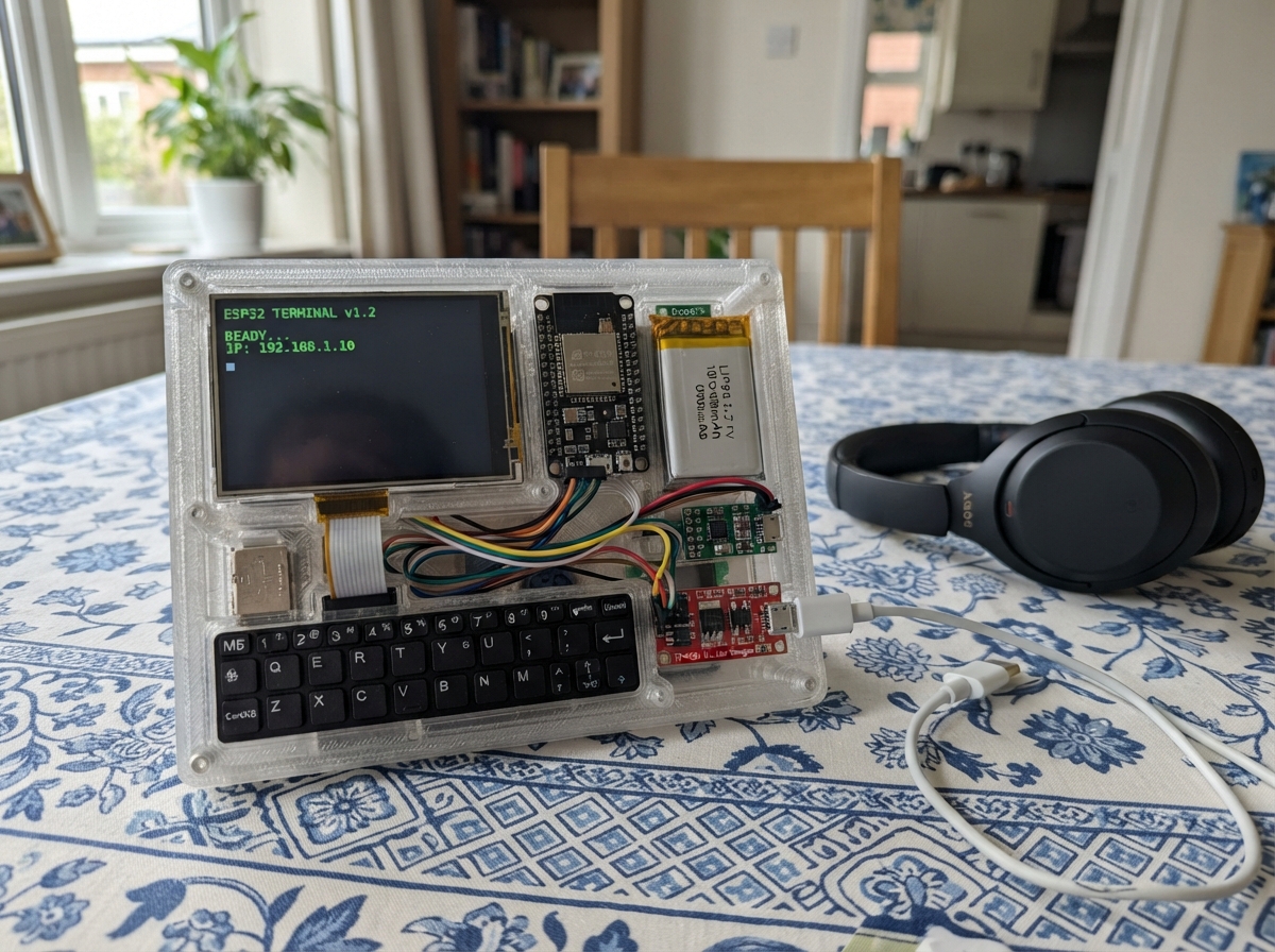
This project turns a Raspberry Pi Pico into a portable text editor with a 3.3-inch touchscreen display and compact keyboard. The device runs on a rechargeable LiPo battery managed by a charger module and boost converter, making it truly mobile for quick note-taking or writing on the go.
Builders will receive a complete wiring diagram showing how to connect the ILI9341 display, M5Stack keyboard, and power management components to the Pico, along with a full parts list, Arduino firmware for text editing and touch input, and step-by-step assembly instructions including proper power sequencing and logic level shifting for 5V-tolerant signals.
Wiring diagram

Gather all the parts
Assemble it in 5 steps
1. Prepare the rechargeable power section
With the battery disconnected, connect battery_1 positive (+) to charger_1 B+ and battery_1 negative (−) to charger_1 B−. Connect charger_1 OUT+ to boost_1 VIN+ and charger_1 OUT− to boost_1 VIN−. Use a USB cable only on charger_1 IN+ and IN− when charging.
- Set the boost converter output to exactly 5.0 V with a meter before connecting anything else.
- Do not connect the battery directly to the Raspberry Pi Pico 2 W or the screen — incorrect battery voltage can damage them.
2. Power the Pico, screen, keyboard, and level shifter
Connect boost_1 VOUT+ to the Pico 5 V / VBUS power pin and to keyboard_1 VCC. Connect boost_1 VOUT− to every GND pin: the Pico, tft_1, keyboard_1, and level_shifter_1. Connect the Pico 3V3 pin to tft_1 VCC and TFT_BL, and to level_shifter_1 LV. Connect boost_1 VOUT+ to level_shifter_1 HV.
- All ground wires must meet; they give every signal a common reference.
- Make sure VCC and GND are not swapped on the screen or level-shifter — swapped power can damage them.
3. Wire the screen to the Pico
Connect tft_1 MOSI to Pico GP19 (screen data), MISO to GP16 (screen return data), SCK to GP18 (screen timing), TFT_CS to GP17 (screen select), TFT_DC to GP6 (screen command/data), TFT_RST to GP7 (screen reset), and TOUCH_CS to GP8 (touch select).
- Keep these screen wires short and check each printed label before powering up.
- Do not move the screen's VCC wire to the 5 V boost output; this display is powered from the Pico's 3.3 V pin.
4. Put the keyboard signals through the level shifter
Connect Pico GP4 to level_shifter_1 LV1 and Pico GP5 to level_shifter_1 LV2. Connect keyboard_1 SDA to the matching high-side channel HV1 and keyboard_1 SCL to the matching high-side channel HV2. The level-shifter board labels may use HV1/HV2 rather than one shared HV1-HV4 label.
- Keep SDA paired with LV1/HV1 and SCL paired with LV2/HV2; do not cross the two channels.
- Do not connect the keyboard SDA or SCL pins directly to the Pico. The keyboard's 5 V signal level can damage the Pico's 3.3 V pins.
5. Check before first power-up
Check that the battery polarity is correct, the boost output is 5.0 V, the screen is on 3.3 V, and every module has a GND wire. Then plug the Pico into USB for its first test.
- If the screen stays blank, disconnect power first and recheck the six screen signal wires one at a time.
- Never charge the battery through the boost converter output; charge it only through the TP4056 module's USB input.
Review all connections
1. Connections between "tft_1" and "Raspberry Pi Pico"
2. Connections between "keyboard_1" and "Raspberry Pi Pico"
3. Connections between "battery_1" and "Raspberry Pi Pico"
4. Connections between "charger_1" and "Raspberry Pi Pico"
5. Connections between "boost_1" and "Raspberry Pi Pico"
6. Connections between "level_shifter_1" and "Raspberry Pi Pico"
Deploy the firmware
#include <Arduino.h>
#include <SPI.h>
#include <Wire.h>
#include <Adafruit_GFX.h>
#include <Adafruit_ILI9341.h>
#include <XPT2046_Touchscreen.h>


// Forward declarations
void drawLine(uint8_t line);
void drawCursor();
void redrawNote();
void clearNote();
void newLine();
void appendCharacter(char key);
char readKeyboard();

constexpr uint8_t TFT_CS_PIN = 17;
constexpr uint8_t TFT_DC_PIN = 6;
constexpr uint8_t TFT_RST_PIN = 7;
constexpr uint8_t TOUCH_CS_PIN = 8;
constexpr uint8_t TFT_MOSI_PIN = 19;
constexpr uint8_t TFT_MISO_PIN = 16;
constexpr uint8_t TFT_SCK_PIN = 18;
constexpr uint8_t KEYBOARD_SDA_PIN = 4;
constexpr uint8_t KEYBOARD_SCL_PIN = 5;
constexpr uint8_t KEYBOARD_ADDRESS = 0x5F;

constexpr int16_t SCREEN_W = 320;
constexpr int16_t SCREEN_H = 240;
constexpr int16_t HEADER_H = 26;
constexpr int16_t FOOTER_H = 18;
constexpr int16_t TEXT_X = 8;
constexpr int16_t TEXT_Y = 36;
constexpr int16_t CHAR_W = 6;
constexpr int16_t LINE_H = 10;
constexpr uint8_t MAX_COLS = 50;
constexpr uint8_t MAX_LINES = 18;
constexpr uint16_t HEADER_COLOR = 0x000F;
constexpr uint16_t FOOTER_COLOR = 0x7BEF;

Adafruit_ILI9341 tft(TFT_CS_PIN, TFT_DC_PIN, TFT_RST_PIN);
XPT2046_Touchscreen touch(TOUCH_CS_PIN);
char noteLines[MAX_LINES][MAX_COLS + 1];
uint8_t cursorLine = 0;
uint8_t cursorCol = 0;
unsigned long lastKeyPoll = 0;
unsigned long lastTouchPoll = 0;

void drawLine(uint8_t line) {
  const int16_t y = TEXT_Y + line * LINE_H;
  tft.fillRect(0, y, SCREEN_W, LINE_H, ILI9341_BLACK);
  tft.setTextColor(ILI9341_GREEN, ILI9341_BLACK);
  tft.setTextSize(1);
  tft.setCursor(TEXT_X, y + 1);
  tft.print(noteLines[line]);
}

void drawCursor() {
  const int16_t x = TEXT_X + cursorCol * CHAR_W;
  const int16_t y = TEXT_Y + cursorLine * LINE_H;
  tft.drawFastVLine(x, y, LINE_H - 1, ILI9341_YELLOW);
}

void redrawNote() {
  tft.fillRect(0, HEADER_H, SCREEN_W, SCREEN_H - HEADER_H - FOOTER_H, ILI9341_BLACK);
  for (uint8_t line = 0; line < MAX_LINES; line++) drawLine(line);
  drawCursor();
}

void clearNote() {
  for (uint8_t line = 0; line < MAX_LINES; line++) noteLines[line][0] = '\0';
  cursorLine = 0;
  cursorCol = 0;
  redrawNote();
}

void newLine() {
  if (cursorLine < MAX_LINES - 1) {
    cursorLine++;
    cursorCol = 0;
    drawCursor();
  }
}

void appendCharacter(char key) {
  if (key == '\r' || key == '\n') {
    newLine();
    return;
  }
  if (key == 8 || key == 127) {
    if (cursorCol > 0) {
      cursorCol--;
      noteLines[cursorLine][cursorCol] = '\0';
      drawLine(cursorLine);
      drawCursor();
    }
    return;
  }
  if (key < 32 || key > 126) return;
  if (cursorCol >= MAX_COLS) newLine();
  if (cursorCol < MAX_COLS) {
    noteLines[cursorLine][cursorCol++] = key;
    noteLines[cursorLine][cursorCol] = '\0';
    drawLine(cursorLine);
    drawCursor();
  }
}

char readKeyboard() {
  Wire.beginTransmission(KEYBOARD_ADDRESS);
  if (Wire.endTransmission() != 0) return 0;
  if (Wire.requestFrom((int)KEYBOARD_ADDRESS, 1) != 1) return 0;
  return (char)Wire.read();
}

void setup() {
#if defined(ARDUINO_ARCH_RP2040)
  // Route the Pico 2 W hardware buses to the pins used by this build.
  SPI.setSCK(TFT_SCK_PIN);
  SPI.setTX(TFT_MOSI_PIN);
  SPI.setRX(TFT_MISO_PIN);
#endif
  SPI.begin();
  Wire.begin();
  Wire.setClock(100000);

  tft.begin();
  tft.setRotation(1);
  touch.begin();
  touch.setRotation(1);
  tft.fillScreen(ILI9341_BLACK);
  tft.fillRect(0, 0, SCREEN_W, HEADER_H, HEADER_COLOR);
  tft.setTextColor(ILI9341_WHITE, HEADER_COLOR);
  tft.setTextSize(2);
  tft.setCursor(8, 5);
  tft.print("Pocket Writer");
  tft.fillRect(0, SCREEN_H - FOOTER_H, SCREEN_W, FOOTER_H, FOOTER_COLOR);
  tft.setTextColor(ILI9341_WHITE, FOOTER_COLOR);
  tft.setTextSize(1);
  tft.setCursor(8, SCREEN_H - FOOTER_H + 5);
  tft.print("Type on keyboard | Touch screen to clear");
  clearNote();
}

void loop() {
  const unsigned long now = millis();
  if (now - lastKeyPoll >= 25) {
    lastKeyPoll = now;
    const char key = readKeyboard();
    if (key != 0) appendCharacter(key);
  }
  if (now - lastTouchPoll >= 50) {
    lastTouchPoll = now;
    if (touch.touched()) {
      clearNote();
      delay(200);
    }
  }
}
Remix this project
Make it yours in one click
Open a full copy of this project in your own Schematik workspace — diagram, code, parts, and assembly steps included. Swap the sensor, add features, or redesign the whole thing with AI. The author's original stays untouched.
Related projects
Fridge Scale Smart Clip
Raspberry Pi Pico · September 14, 2026Phillip Knopp
Tiny Robot AI Assistant
Raspberry Pi Pico · September 13, 2026Shaikh Tajmul haque
Tiny Spider Robot
Raspberry Pi Pico · September 13, 2026Shaikh Tajmul haque