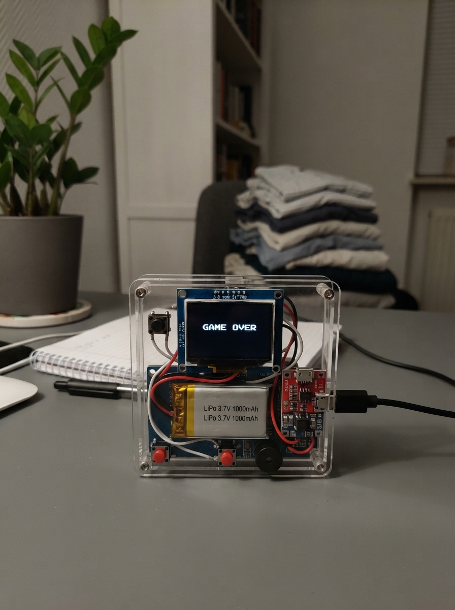
Build a pocket-sized retro game console powered by an ESP32 microcontroller and a vibrant 2-inch ST7789 color display. This portable device features directional controls, action buttons, and audio feedback via a piezo buzzer, all powered by a rechargeable LiPo battery with integrated charging and protection circuitry.
This guide provides a complete wiring diagram, full parts list, and step-by-step assembly instructions to get the console running. The included firmware implements a classic snake game with score tracking and sound effects, serving as a foundation for adding additional retro games. Learn how to integrate the display, button matrix, audio output, and power management into a compact handheld device.
Wiring diagram
Gather all the parts
Assemble it in 6 steps
1. Préparer le boîtier et les commandes
Fixez l’écran screen au centre de la face avant. Placez les quatre boutons dpad_up, dpad_down, dpad_left et dpad_right en croix à gauche, puis button_a, button_b et button_start à droite. Chaque bouton doit rester accessible une fois le boîtier fermé.
- Les boutons ont deux paires de pattes reliées entre elles : utilisez une patte de chaque côté du bouton, pas deux pattes du même côté.
2. Relier l’écran couleur
Avec la console hors tension, reliez VCC du screen à 3V3 (alimentation), GND à GND (masse), SCK à GPIO18 (horloge), MOSI à GPIO23 (données), CS à GPIO19 (sélection), DC à GPIO16 (données ou commande) et RST à GPIO17 (remise à zéro).
- Ne branchez jamais VCC et GND à l’envers : l’écran peut être endommagé.
3. Câbler les boutons
Pour chaque bouton, reliez une patte à GND (masse). Reliez l’autre patte de dpad_up à GPIO13 (haut), dpad_down à GPIO14 (bas), dpad_left à GPIO25 (gauche), dpad_right à GPIO26 (droite), button_a à GPIO27 (action), button_b à GPIO32 (pause) et button_start à GPIO33 (démarrer ou recommencer).
- Le programme utilise les résistances internes de la carte : aucun petit composant supplémentaire n’est nécessaire pour les boutons.
4. Ajouter le son
Reliez SIG du buzzer à GPIO22 (son) et son autre patte GND à GND (masse). Le piezo n’a pas de polarité, donc ses deux pattes peuvent être inversées.
5. Assembler l’alimentation rechargeable
Reliez +V de battery à B+ de charger (batterie positive) et GND de battery à B− de charger (batterie négative). Reliez OUT+ du charger à VIN+ de boost (énergie protégée) et OUT− à VIN− de boost (retour). Réglez boost à exactement 5,0 V avec un multimètre avant de le relier : VOUT+ va sur VIN/5V de l’ESP32 (alimentation) et VOUT− va sur GND (masse).
- Une batterie LiPo ne doit jamais être percée, écrasée ni connectée à l’envers : elle peut chauffer ou prendre feu.
- Ne branchez pas le convertisseur sur l’ESP32 avant d’avoir mesuré 5,0 V à sa sortie ; une tension trop élevée peut détruire la carte.
6. Prévoir la recharge et fermer
Laissez le port USB du charger accessible par une ouverture du boîtier : son entrée IN+ et IN− reçoit le câble USB de recharge. Vérifiez qu’aucun fil nu ne touche un autre fil, fixez la batterie pour qu’elle ne bouge pas, puis fermez le boîtier sans pincer les câbles.
- Ne rechargez pas la batterie sans surveillance sur une surface inflammable.
Review all connections
1. Connections between "screen" and "ESP32"
2. Connections between "dpad_up" and "ESP32"
3. Connections between "dpad_down" and "ESP32"
4. Connections between "dpad_left" and "ESP32"
5. Connections between "dpad_right" and "ESP32"
6. Connections between "button_a" and "ESP32"
7. Connections between "button_b" and "ESP32"
8. Connections between "button_start" and "ESP32"
9. Connections between "buzzer" and "ESP32"
10. Connections between "battery" and "ESP32"
11. Connections between "charger" and "ESP32"
12. Connections between "boost" and "ESP32"
Deploy the firmware
#include <Arduino.h>
#include <SPI.h>
#include <Adafruit_GFX.h>
#include <Adafruit_ST7789.h>

constexpr int TFT_CS = 19;
constexpr int TFT_DC = 16;
constexpr int TFT_RST = 17;
constexpr int BTN_UP = 13;
constexpr int BTN_DOWN = 14;
constexpr int BTN_LEFT = 25;
constexpr int BTN_RIGHT = 26;
constexpr int BTN_A = 27;
constexpr int BTN_B = 32;
constexpr int BTN_START = 33;
constexpr int BUZZER_PIN = 22;

constexpr int SCREEN_W = 320;
constexpr int SCREEN_H = 240;
constexpr int CELL = 10;
constexpr int FIELD_X = 10;
constexpr int FIELD_Y = 30;
constexpr int FIELD_W = 300;
constexpr int FIELD_H = 200;
constexpr int COLS = FIELD_W / CELL;
constexpr int ROWS = FIELD_H / CELL;
constexpr int MAX_SNAKE = COLS * ROWS;
constexpr uint16_t BG = ST77XX_BLACK;
constexpr uint16_t SNAKE = ST77XX_GREEN;
constexpr uint16_t FOOD = ST77XX_RED;

Adafruit_ST7789 tft(TFT_CS, TFT_DC, TFT_RST);

struct Cell { int8_t x; int8_t y; };
Cell snake[MAX_SNAKE];
Cell food;
int snakeLength = 4;
int dx = 1;
int dy = 0;
int score = 0;
bool paused = false;
bool gameOver = false;
unsigned long lastMove = 0;
const unsigned long MOVE_MS = 120;

bool wasPressed(int pin) {
  static bool previous[40] = {false};
  bool now = digitalRead(pin) == LOW;
  bool pressed = now && !previous[pin];
  previous[pin] = now;
  return pressed;
}

void beep(uint16_t frequency, uint16_t duration) {
  tone(BUZZER_PIN, frequency, duration);
}

void drawCell(const Cell &c, uint16_t color) {
  tft.fillRect(FIELD_X + c.x * CELL + 1, FIELD_Y + c.y * CELL + 1, CELL - 2, CELL - 2, color);
}

bool snakeContains(int x, int y) {
  for (int i = 0; i < snakeLength; ++i) {
    if (snake[i].x == x && snake[i].y == y) return true;
  }
  return false;
}

void placeFood() {
  do {
    food.x = random(COLS);
    food.y = random(ROWS);
  } while (snakeContains(food.x, food.y));
  drawCell(food, FOOD);
}

void drawScore() {
  tft.fillRect(0, 0, SCREEN_W, 28, ST77XX_BLACK);
  tft.setTextColor(ST77XX_CYAN, ST77XX_BLACK);
  tft.setTextSize(2);
  tft.setCursor(10, 6);
  tft.print("RETRO SNAKE  ");
  tft.print(score);
}

void resetGame() {
  tft.fillScreen(BG);
  tft.drawRect(FIELD_X - 1, FIELD_Y - 1, FIELD_W + 2, FIELD_H + 2, ST77XX_BLUE);
  snakeLength = 4;
  score = 0;
  dx = 1;
  dy = 0;
  paused = false;
  gameOver = false;
  for (int i = 0; i < snakeLength; ++i) {
    snake[i] = {static_cast<int8_t>(12 - i), 10};
    drawCell(snake[i], SNAKE);
  }
  drawScore();
  placeFood();
  beep(880, 80);
}

void showGameOver() {
  tft.fillRect(55, 92, 210, 58, ST77XX_BLACK);
  tft.drawRect(55, 92, 210, 58, ST77XX_RED);
  tft.setTextColor(ST77XX_RED, ST77XX_BLACK);
  tft.setTextSize(2);
  tft.setCursor(82, 103);
  tft.print("GAME OVER");
  tft.setTextColor(ST77XX_WHITE, ST77XX_BLACK);
  tft.setTextSize(1);
  tft.setCursor(77, 130);
  tft.print("START pour rejouer");
  beep(180, 280);
}

void handleControls() {
  if (wasPressed(BTN_START)) {
    if (gameOver) resetGame();
    else {
      paused = !paused;
      beep(paused ? 400 : 700, 50);
    }
  }
  if (wasPressed(BTN_UP) && dy != 1) { dx = 0; dy = -1; }
  if (wasPressed(BTN_DOWN) && dy != -1) { dx = 0; dy = 1; }
  if (wasPressed(BTN_LEFT) && dx != 1) { dx = -1; dy = 0; }
  if (wasPressed(BTN_RIGHT) && dx != -1) { dx = 1; dy = 0; }
  if (wasPressed(BTN_A)) { paused = false; beep(1000, 35); }
  if (wasPressed(BTN_B)) { paused = true; beep(400, 35); }
}

void moveSnake() {
  Cell next = {static_cast<int8_t>(snake[0].x + dx), static_cast<int8_t>(snake[0].y + dy)};
  if (next.x < 0 || next.x >= COLS || next.y < 0 || next.y >= ROWS || snakeContains(next.x, next.y)) {
    gameOver = true;
    showGameOver();
    return;
  }
  bool ate = next.x == food.x && next.y == food.y;
  Cell tail = snake[snakeLength - 1];
  if (ate && snakeLength < MAX_SNAKE) {
    for (int i = snakeLength; i > 0; --i) snake[i] = snake[i - 1];
    ++snakeLength;
  } else {
    for (int i = snakeLength - 1; i > 0; --i) snake[i] = snake[i - 1];
  }
  snake[0] = next;
  if (ate) {
    ++score;
    drawScore();
    beep(1200, 55);
    placeFood();
  } else {
    drawCell(tail, BG);
  }
  drawCell(snake[0], SNAKE);
}

void setup() {
  const int buttons[] = {BTN_UP, BTN_DOWN, BTN_LEFT, BTN_RIGHT, BTN_A, BTN_B, BTN_START};
  for (int pin : buttons) pinMode(pin, INPUT_PULLUP);
  pinMode(BUZZER_PIN, OUTPUT);
  randomSeed(esp_random());
  tft.init(240, 320);
  tft.setRotation(1);
  resetGame();
}

void loop() {
  handleControls();
  unsigned long now = millis();
  if (!paused && !gameOver && now - lastMove >= MOVE_MS) {
    lastMove = now;
    moveSnake();
  }
  delay(5);
}
Remix this project
Make it yours in one click
Open a full copy of this project in your own Schematik workspace, diagram, code, parts, and assembly steps included. Swap the sensor, add features, or redesign the whole thing with AI. The author's original stays untouched.