Community project
Portable Secure EV Charging Station
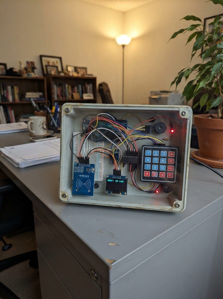
This project demonstrates a tabletop theft-protection system for portable electronics, combining RFID card authentication with PIN verification to control access to a docked device. The system uses an ESP32 microcontroller to manage a servo-controlled latch, vibration detection, status display, and alarm functions, making it ideal for showcasing secure device management in maker spaces or educational settings.
The guide provides a complete wiring diagram, parts list, and step-by-step assembly instructions for building both the dock station and portable unit. Firmware is included to handle RFID scanning, keypad input, servo locking/release logic, tamper detection via vibration sensor, and wireless communication between the dock and portable components. The system runs on solar charging with a Li-ion battery backup, making it a self-contained demonstration of authentication and physical security integration.
Wiring diagram

Gather all the parts
Assemble it in 8 steps
1. Prepare the two boxes
Use a 60 × 30 × 30 cm dock and a 30 × 20 × 30 cm portable box. Mount the keypad, RFID reader, screen, alarm and spring latch in the dock. Mount the portable ESP32, battery, charger, converters, GPS and GSM module in the removable box. Keep antenna areas free of metal.
2. Fit the solar and USB-C charging inputs
Mount the USB-C socket where a mobile charging cable can reach it. Connect its VBUS pin to selector USB (5 V backup power) and its GND to the shared ground (return). Connect CC1 through one 5.1 kΩ resistor to GND, and CC2 through the other 5.1 kΩ resistor to GND; these two small resistors make a USB-C-to-USB-C phone charger turn on. For each panel, connect PV+ to one diode's unstriped end (solar power). Join the five striped ends to selector SOLAR (solar input), and join panel negatives to ground (return). Connect selector COMMON to charger IN+ (selected charging power), charger IN− to ground (return), BAT+ to battery BAT+ (battery power), and BAT− to battery BAT− (return).
- Use a ready-made USB-C 5 V input/sink breakout with the two 5.1 kΩ resistors already fitted if possible; then do not add separate resistors a second time.
- Never join the solar positive and USB-C positive wires directly; the selector chooses one source.
- Never reverse the battery leads. Reversed battery power can damage the charger or battery.
3. Connect the portable electronics
Connect charger SYS+ to boost IN+ (power) and SYS− to boost IN− (return). Connect boost OUT+ to portable ESP32 VIN (5 V power) and OUT− to its GND (return). Connect motion sensor VIN and GPS VCC to portable 3V3 (power), their GND pins to portable GND (return), sensor SDA to GPIO21 (data), SCL to GPIO22 (clock) and GPS TX to GPIO25 (location data).
4. Connect the GSM supply
Connect GSM supply IN+ to charger SYS+ (power) and IN− to SYS− (return). Measure and set its output to 4.0 V before connecting OUT+ to modem VCC (power) and OUT− to modem GND (return). Connect capacitor + to modem VCC (burst support), and striped negative lead to modem GND (return). Connect modem TX to portable GPIO16 (replies). Connect GPIO17 to the 1 kΩ resistor, its other end to modem RX (commands), and the 5.6 kΩ resistor from RX to portable GND (signal voltage reduction). Attach the antenna and install an active SMS-capable 2G SIM with power disconnected.
- Reversing the capacitor can make it burst. Keep GSM power wires short and off breadboards.
5. Connect the dock controls
Connect dock adapter 5V+ to dock VIN (power) and GND to dock GND (return). Connect OLED VCC and expander VDD to 3V3 (power), their grounds to GND (return), SDA to GPIO21 (data) and SCL to GPIO22 (clock). Connect RFID VCC to 3V3 (power), GND to GND (return), SCK to GPIO18 (clock), MOSI to GPIO23 (data), MISO to GPIO19 (data), SDA/SS to GPIO4 (select) and RST to GPIO13 (reset).
- 5 V can damage the RFID reader; use 3.3 V.
6. Connect the latch and alarms
Align the spring bolt with the portable box slot; arrange the servo horn to retract it without binding. Connect servo VCC to dock 5 V (power), GND to dock GND (return) and signal to GPIO14 (control). Connect keypad rows to expander GPA0–3 (row signals) and columns to GPA4–7 (column signals). Connect vibration VCC to 3V3 (power), GND to GND (return), DO to GPB0 (movement signal). Connect buzzer signal to GPIO27 (alarm) and GND to ground (return). Connect GPIO32 through a 220 Ω resistor to red LED anode (locked indicator), GPIO33 through the other resistor to green anode (release indicator), and both LED cathodes to GND (return).
- Keep fingers away from the moving latch. The 3.3 V servo signal has a level-mismatch warning; a suitable level converter may be needed.
7. Fit the USB-A output
Mount portable_usb_a_1 securely in the portable enclosure. Solder boost OUT+ to usb_output_fuse_1 IN (5 V power), fuse OUT to USB VCC (fused power), and USB GND to boost OUT− (return). Leave USB D+ and D− unconnected and insulated (no data). With the toy unplugged, measure about 5 V between USB VCC and GND. Use a USB-A-to-USB-C cable to a toy with its own 5 V charging circuit.
- Never connect this port to a computer or another power source; this is an output only.
- Do not connect directly to a toy battery or motor.
8. Check the physical installation
Secure all modules and insulate exposed battery and USB power joints. Check that the latch moves freely, the antennas are attached, and the portable box can be removed without pulling wires. Take the GPS antenna outdoors for its first location test.
- This is a low-voltage demonstrator, not a scooter charger or a security-grade vehicle lock.
Review all connections
1. Connections between "rfid_1" and "ESP32"
2. Connections between "vibration_1" and "ESP32"
3. Connections between "oled_1" and "ESP32"
4. Connections between "ioexpander_1" and "ESP32"
5. Connections between "keypad_1" and "ESP32"
6. Connections between "buzzer_1" and "ESP32"
7. Connections between "red_resistor_1" and "ESP32"
8. Connections between "status_red_1" and "ESP32"
9. Connections between "green_resistor_1" and "ESP32"
10. Connections between "status_green_1" and "ESP32"
11. Connections between "mini_solar_1" and "ESP32"
12. Connections between "source_selector_1" and "ESP32"
13. Connections between "solar_lipo_charger_1" and "ESP32"
14. Connections between "boost_5v_1" and "ESP32"
15. Connections between "dock_servo_1" and "ESP32"
16. Connections between "dock_usb_adapter_1" and "ESP32"
17. Connections between "portable_imu_1" and "ESP32"
18. Connections between "sim808_power_1" and "ESP32"
19. Connections between "sim808_reservoir_cap_1" and "ESP32"
20. Connections between "portable_sim808_1" and "ESP32"
21. Connections between "sim800_uart_top_resistor_1" and "ESP32"
22. Connections between "sim800_uart_bottom_resistor_1" and "ESP32"
23. Connections between "portable_gps_1" and "ESP32"
24. Connections between "solar_blocking_diode_1" and "ESP32"
25. Connections between "usb_output_fuse_1" and "ESP32"
26. Connections between "portable_usb_a_1" and "ESP32"
27. Connections between "usb_c_input_1" and "ESP32"
28. Connections between "usb_c_cc1_resistor_1" and "ESP32"
29. Connections between "usb_c_cc2_resistor_1" and "ESP32"
30. Connections between "servo_level_shifter_1" and "ESP32"
31. Connections between "servo_bulk_cap_1" and "ESP32"
32. Connections between "dock_charge_switch_1" and "ESP32"
33. Connections between "dock_charge_en_resistor_1" and "ESP32"
34. Connections between "portable_charge_plug_1" and "ESP32"
Deploy the firmware
#include <Arduino.h>
#include <Wire.h>
#include <SPI.h>
#include <MFRC522.h>
#include <Adafruit_GFX.h>
#include <Adafruit_SSD1306.h>
#include <Adafruit_MCP23X17.h>
#include <ESP32Servo.h>
#include <WiFi.h>
#include <esp_now.h>

// Tabletop theft-protection demonstrator.
// Docked = servo at LOCK_ANGLE. After an approved RFID card and PIN,
// the servo moves to RELEASE_ANGLE so the small unit can be removed.


// Forward declarations
void showStatus(const String &line1, const String &line2);
void lockDock(const String &reason);
void releaseDock();
void startAlarm(const String &reason);
void serviceAlarm();
String cardUid();
void pollRfid();
char scanKeypad();
void pollKeypad();
void pollTamper();
void beginRadio();
void sendPortableRelease();

constexpr uint8_t SERVO_PIN = 14;
constexpr uint8_t CHARGE_ENABLE_PIN = 26;
constexpr uint8_t BUZZER_PIN = 27;
constexpr uint8_t RED_LED_PIN = 32;
constexpr uint8_t GREEN_LED_PIN = 33;
constexpr uint8_t RFID_SS_PIN = 4;
constexpr uint8_t RFID_RST_PIN = 13;
constexpr uint8_t RFID_SCK_PIN = 18;
constexpr uint8_t RFID_MISO_PIN = 19;
constexpr uint8_t RFID_MOSI_PIN = 23;
constexpr uint8_t I2C_SDA_PIN = 21;
constexpr uint8_t I2C_SCL_PIN = 22;
constexpr uint8_t OLED_ADDR = 0x3C;
constexpr uint8_t MCP_ADDR = 0x20;
constexpr uint8_t ROW_COUNT = 4;
constexpr uint8_t COLUMN_BASE = 4;
constexpr uint8_t VIBRATION_INPUT = 8; // MCP GPB0
constexpr int LOCK_ANGLE = 15;
constexpr int RELEASE_ANGLE = 100;
constexpr unsigned long CARD_WINDOW_MS = 30000UL;
constexpr unsigned long RELEASE_WINDOW_MS = 15000UL;
// Change both credentials before deployment.
const char AUTHORIZED_RFID_UID[] = "DEADBEEF";
const char RELEASE_PIN[] = "2580";
const char PROJECT_KEY[] = "SSPCU-DEMO-2026";
const uint8_t PORTABLE_BROADCAST_MAC[] = {0xFF, 0xFF, 0xFF, 0xFF, 0xFF, 0xFF};

struct __attribute__((packed)) RadioPacket {
  char key[20];
  char event[12];
};

bool portableOnline = false;

const char KEYMAP[4][4] = {
  {'1', '2', '3', 'A'},
  {'4', '5', '6', 'B'},
  {'7', '8', '9', 'C'},
  {'*', '0', '#', 'D'}
};

Adafruit_SSD1306 display(128, 64, &Wire, -1);
Adafruit_MCP23X17 mcp;
MFRC522 rfid(RFID_SS_PIN, RFID_RST_PIN);
Servo dockServo;

bool cardAccepted = false;
bool released = false;
bool alarmActive = false;
String enteredPin;
String shownLine1;
String shownLine2;
unsigned long cardAcceptedAt = 0;
unsigned long releasedAt = 0;
unsigned long lastAlarmToneAt = 0;

void showStatus(const String &line1, const String &line2) {
  if (line1 == shownLine1 && line2 == shownLine2) return;
  shownLine1 = line1;
  shownLine2 = line2;
  display.clearDisplay();
  display.setTextColor(SSD1306_WHITE);
  display.setTextSize(1);
  display.setCursor(0, 0);
  display.println("SSPCU MINI DOCK");
  display.drawFastHLine(0, 11, 128, SSD1306_WHITE);
  display.setCursor(0, 18);
  display.println(line1);
  display.setCursor(0, 34);
  display.println(line2);
  display.setCursor(0, 52);
  display.println(released ? "LATCH: RELEASED" : "LATCH: LOCKED");
  display.display();
}

void lockDock(const String &reason) {
  released = false;
  cardAccepted = false;
  enteredPin = "";
  dockServo.write(LOCK_ANGLE);
  digitalWrite(CHARGE_ENABLE_PIN, HIGH);
  digitalWrite(GREEN_LED_PIN, LOW);
  digitalWrite(RED_LED_PIN, HIGH);
  showStatus("DOCK LOCKED", reason);
}

void releaseDock() {
  released = true;
  alarmActive = false;
  // Remove charging power before the latch can release the portable unit.
  digitalWrite(CHARGE_ENABLE_PIN, LOW);
  sendPortableRelease();
  releasedAt = millis();
  dockServo.write(RELEASE_ANGLE);
  digitalWrite(RED_LED_PIN, LOW);
  digitalWrite(GREEN_LED_PIN, HIGH);
  tone(BUZZER_PIN, 2200, 120);
  showStatus("ACCESS APPROVED", "REMOVE UNIT NOW");
}

void startAlarm(const String &reason) {
  if (released || alarmActive) return;
  alarmActive = true;
  showStatus("TAMPER ALARM", reason);
}

void serviceAlarm() {
  if (!alarmActive) return;
  if (millis() - lastAlarmToneAt >= 800UL) {
    lastAlarmToneAt = millis();
    tone(BUZZER_PIN, 3000, 260);
    digitalWrite(RED_LED_PIN, !digitalRead(RED_LED_PIN));
  }
}

String cardUid() {
  String uid;
  for (byte i = 0; i < rfid.uid.size; ++i) {
    if (rfid.uid.uidByte[i] < 0x10) uid += '0';
    uid += String(rfid.uid.uidByte[i], HEX);
  }
  uid.toUpperCase();
  return uid;
}

void onRadioReceive(const esp_now_recv_info_t *, const uint8_t *data, int length) {
  if (length != sizeof(RadioPacket)) return;
  RadioPacket packet{};
  memcpy(&packet, data, sizeof(packet));
  if (strcmp(packet.key, PROJECT_KEY) != 0) return;
  if (strcmp(packet.event, "ONLINE") == 0 || strcmp(packet.event, "ACK") == 0) portableOnline = true;
  if (strcmp(packet.event, "TAMPER") == 0) startAlarm("PORTABLE UNIT MOVED");
}

void beginRadio() {
  WiFi.mode(WIFI_STA);
  if (esp_now_init() != ESP_OK) return;
  esp_now_register_recv_cb(onRadioReceive);
  esp_now_peer_info_t peer{};
  memcpy(peer.peer_addr, PORTABLE_BROADCAST_MAC, 6);
  peer.channel = 0;
  peer.encrypt = false;
  esp_now_add_peer(&peer);
}

void sendPortableRelease() {
  RadioPacket packet{};
  strncpy(packet.key, PROJECT_KEY, sizeof(packet.key) - 1);
  strncpy(packet.event, "RELEASE", sizeof(packet.event) - 1);
  esp_now_send(PORTABLE_BROADCAST_MAC, reinterpret_cast<const uint8_t *>(&packet), sizeof(packet));
}

void pollRfid() {
  if (!rfid.PICC_IsNewCardPresent() || !rfid.PICC_ReadCardSerial()) return;
  const String uid = cardUid();
  rfid.PICC_HaltA();
  rfid.PCD_StopCrypto1();
  if (uid == AUTHORIZED_RFID_UID) {
    cardAccepted = true;
    cardAcceptedAt = millis();
    enteredPin = "";
    tone(BUZZER_PIN, 1700, 70);
    showStatus("RFID ACCEPTED", "TYPE PIN, THEN #");
  } else {
    tone(BUZZER_PIN, 300, 200);
    showStatus("UNKNOWN RFID", "ACCESS DENIED");
  }
}

char scanKeypad() {
  for (uint8_t row = 0; row < ROW_COUNT; ++row) {
    for (uint8_t pin = 0; pin < ROW_COUNT; ++pin) mcp.digitalWrite(pin, HIGH);
    mcp.digitalWrite(row, LOW);
    delayMicroseconds(80);
    for (uint8_t column = 0; column < ROW_COUNT; ++column) {
      if (mcp.digitalRead(COLUMN_BASE + column) == LOW) {
        delay(25); // a quick tap counts once
        while (mcp.digitalRead(COLUMN_BASE + column) == LOW) delay(2);
        mcp.digitalWrite(row, HIGH);
        return KEYMAP[row][column];
      }
    }
    mcp.digitalWrite(row, HIGH);
  }
  return 0;
}

void pollKeypad() {
  const char key = scanKeypad();
  if (!key) return;
  if (key == 'D') {
    lockDock("MANUAL LOCK");
    return;
  }
  if (key == '*') {
    enteredPin = "";
    showStatus("PIN CLEARED", "TYPE PIN, THEN #");
    return;
  }
  if (key >= '0' && key <= '9' && enteredPin.length() < 8) {
    enteredPin += key;
    String masked;
    for (size_t i = 0; i < enteredPin.length(); ++i) masked += '*';
    showStatus(cardAccepted ? "PIN ENTERED" : "PRESENT RFID FIRST", masked);
    return;
  }
  if (key == '#') {
    if (cardAccepted && enteredPin == RELEASE_PIN) {
      releaseDock();
    } else {
      tone(BUZZER_PIN, 300, 250);
      showStatus("PIN DENIED", "DOCK STAYS LOCKED");
    }
    enteredPin = "";
  }
}

void pollTamper() {
  if (mcp.digitalRead(VIBRATION_INPUT) == HIGH) startAlarm("VIBRATION DETECTED");
}

void setup() {
  pinMode(BUZZER_PIN, OUTPUT);
  pinMode(CHARGE_ENABLE_PIN, OUTPUT);
  digitalWrite(CHARGE_ENABLE_PIN, LOW);
  pinMode(RED_LED_PIN, OUTPUT);
  pinMode(GREEN_LED_PIN, OUTPUT);
  digitalWrite(RED_LED_PIN, HIGH);
  digitalWrite(GREEN_LED_PIN, LOW);

  Wire.begin(I2C_SDA_PIN, I2C_SCL_PIN);
  beginRadio();
  display.begin(SSD1306_SWITCHCAPVCC, OLED_ADDR);
  showStatus("STARTING", "KEEP DOCK CLOSED");

  mcp.begin_I2C(MCP_ADDR, &Wire);
  for (uint8_t pin = 0; pin < ROW_COUNT; ++pin) {
    mcp.pinMode(pin, OUTPUT);
    mcp.digitalWrite(pin, HIGH);
  }
  for (uint8_t pin = COLUMN_BASE; pin < VIBRATION_INPUT; ++pin) mcp.pinMode(pin, INPUT_PULLUP);
  mcp.pinMode(VIBRATION_INPUT, INPUT);

  SPI.begin(RFID_SCK_PIN, RFID_MISO_PIN, RFID_MOSI_PIN, RFID_SS_PIN);
  rfid.PCD_Init();
  dockServo.setPeriodHertz(50);
  dockServo.attach(SERVO_PIN, 500, 2400);
  lockDock("PRESENT RFID CARD");
}

void loop() {
  pollRfid();
  pollKeypad();
  pollTamper();
  serviceAlarm();

  if (cardAccepted && !released && millis() - cardAcceptedAt > CARD_WINDOW_MS) {
    lockDock("CARD TIMEOUT");
  }
  if (released && millis() - releasedAt > RELEASE_WINDOW_MS) {
    lockDock("RELEASE TIMEOUT");
  }
}
Remix this project
Make it yours in one click
Open a full copy of this project in your own Schematik workspace — diagram, code, parts, and assembly steps included. Swap the sensor, add features, or redesign the whole thing with AI. The author's original stays untouched.