Community project
Solar Panel Tracking Cleaner
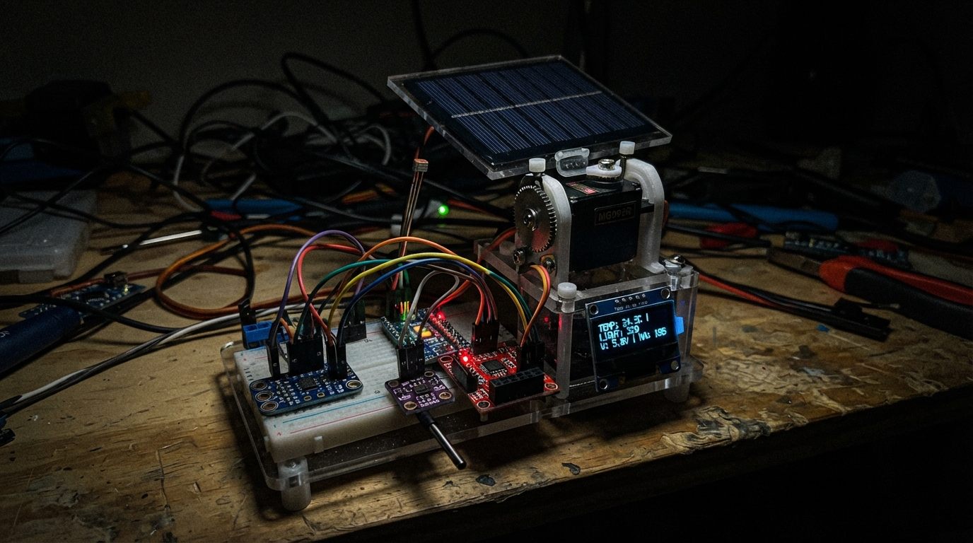
This project combines solar tracking with automated panel cleaning to maximize energy generation. The system uses four light-dependent resistors to track the sun's position across the sky, adjusting azimuth and elevation servos to keep the panel optimally oriented. When dust accumulation reduces output below a threshold detected by the INA219 current sensor, a motorized cleaner automatically traverses the panel surface.
Builders will receive a complete wiring diagram, parts list, and step-by-step assembly instructions covering mechanical mounting, light-sensing divider construction, low-voltage sensor integration, and power distribution. The ESP32 firmware handles dual-axis sun tracking, dust detection via current monitoring, temperature sensing with the BME280 and DS18B20, and automated cleaning cycles with end-switch safety limits.
Wiring diagram

Gather all the parts
Assemble it in 7 steps
1. Mount the moving parts
With all power unplugged, mount the two MG996R servos on the azimuth and elevation brackets. Fit the panel and brush mechanics so neither servo nor brush can hit a hard stop before the matching limit switch is pressed.
- Do not connect servo power while you are fitting arms or linkages — a moving servo can pinch fingers or damage the mechanism.
2. Make the four light-sensing dividers
Place the four GL5528 sensors around a small cross-shaped shade at the panel centre: north-west, north-east, south-west, and south-east. For each one, connect one LDR leg to 3V3 and its other leg to both its matching 10 kΩ resistor and its ESP32 input. Connect the free resistor leg to GND.
- Keep the four LDRs equally exposed except for the small centre shade; this lets unequal light readings show which way the panel should turn.
3. Wire the low-voltage sensors
Connect INA219 VCC and BME280 VCC to 3V3 (power), and both GND pins to GND (ground). Connect both SDA pins to GPIO21 (data) and both SCL pins to GPIO22 (clock). Connect BME280 SDO to GND so it answers at address 0x76. Connect DS18B20 VCC to 3V3 (power), GND to GND (ground), and DATA to GPIO4 (signal). Put the 4.7 kΩ resistor between DATA and 3V3. Connect the 0–3.3 V dust-sensor output to GPIO27 (signal) and its ground to GND.
- Never connect a 5 V dust-sensor output directly to GPIO27 — an ESP32 input is 3.3 V only. Use a verified 0–3.3 V sensor or a correctly calculated divider.
4. Wire the control signals and end switches
Connect the azimuth servo orange signal wire to GPIO25 (signal) and the elevation servo orange signal wire to GPIO26 (signal). Connect TB6612 AIN1 to GPIO16 (direction), AIN2 to GPIO17 (direction), PWMA to GPIO18 (speed signal), and STBY to GPIO19 (enable). Connect each limit-switch COM terminal to GND (ground); connect the home switch NO terminal to GPIO32 (signal) and the far switch NO terminal to GPIO33 (signal). Leave each NC terminal unconnected.
- The program treats a pressed switch as LOW because the switch joins its GPIO to ground.
5. Wire the power branches
Feed the 12 V supply into the two buck converters. Set and measure the servo converter at exactly 6.0 V before connecting the servos. Connect its VOUT+ to both servo red wires (power), VOUT- to both servo brown wires (ground), and fit the 2200 µF capacitor across the same 6 V rails with its + stripe-free lead on VOUT+ and its marked − lead on VOUT−. Set the logic converter to exactly 5.0 V and connect it to ESP32 VIN (power) and GND (ground). Join all supply negatives at the common GND point. Connect TB6612 VM to fused 12 V, VCC to 3V3, GND to common GND, and A01/A02 to the two brush-motor leads.
- Do not power either MG996R from the ESP32 5 V or 3.3 V pin — current surges can reset or damage the board.
- The TB6612 is only safe if the 12 V brush motor is rated at or below 1.0 A continuous current. Do not connect a higher-current motor to it.
6. Connect the solar monitor separately
Connect the solar panel positive lead to INA219 VIN+ and INA219 VIN− to the monitored PV+ terminal. Connect the panel negative lead and PV− terminal to the common low-current ground reference. Connect the PV+ and PV− terminal only to a correctly rated charger or test load; it is not the ESP32 power input.
- Do not connect the small 6 V solar panel straight to the ESP32 VIN pin or to the 12 V motor rail — sunlight voltage changes and can damage equipment.
7. Check before applying power
With a meter and the 12 V supply still unplugged, check that there is no short between each positive rail and GND. Confirm the logic buck is 5.0 V and the servo buck is 6.0 V. Press each limit switch and confirm it mechanically stops the brush at the correct end. Then power the ESP32 over USB first, connect the 12 V supply, and observe the system with the brush lifted clear of the panel for its first test.
- If the brush travels toward the wrong end, unplug 12 V and swap the two motor leads at A01/A02 or reverse the direction logic — do not let it force against the frame.
Review all connections
1. Connections between "ina219_1" and "ESP32"
2. Connections between "bme280_1" and "ESP32"
3. Connections between "ds18b20_1" and "ESP32"
4. Connections between "ds18b20_pullup" and "ESP32"
5. Connections between "tracker_servo_azimuth" and "ESP32"
6. Connections between "tracker_servo_elevation" and "ESP32"
7. Connections between "servo_bulk_cap" and "ESP32"
8. Connections between "tb6612_1" and "ESP32"
9. Connections between "cleaner_limit_home" and "ESP32"
10. Connections between "cleaner_limit_far" and "ESP32"
11. Connections between "ldr_nw" and "ESP32"
12. Connections between "ldr_resistor_nw" and "ESP32"
13. Connections between "ldr_ne" and "ESP32"
14. Connections between "ldr_resistor_ne" and "ESP32"
15. Connections between "ldr_sw" and "ESP32"
16. Connections between "ldr_resistor_sw" and "ESP32"
17. Connections between "ldr_se" and "ESP32"
18. Connections between "ldr_resistor_se" and "ESP32"
19. Connections between "dust_input" and "ESP32"
20. Connections between "supply_12v" and "ESP32"
21. Connections between "buck_servo_6v" and "ESP32"
22. Connections between "buck_logic_5v" and "ESP32"
23. Connections between "solar_panel_1" and "ESP32"
24. Connections between "pv_monitored_output" and "ESP32"
Deploy the firmware
#include <Wire.h>
#include <Adafruit_INA219.h>
#include <Adafruit_BME280.h>
#include <soc/gpio_struct.h>
#include <OneWire.h>
#include <DallasTemperature.h>
#include <ESP32Servo.h>

#define DS18B20_PIN 4
#define AZIMUTH_SERVO_PIN 25
#define ELEVATION_SERVO_PIN 26
#define TB_AIN1_PIN 16
#define TB_AIN2_PIN 17
#define TB_PWMA_PIN 18
#define TB_STBY_PIN 19
#define CLEANER_HOME_PIN 32
#define CLEANER_FAR_PIN 33
#define LDR_NW_PIN 36
#define LDR_NE_PIN 39
#define LDR_SW_PIN 34
#define LDR_SE_PIN 35
#define DUST_PIN 27

const int SERVO_MIN_DEG = 15;
const int SERVO_MAX_DEG = 165;
const int TRACK_DEADBAND = 120;
const int DUST_CLEAN_THRESHOLD = 2500;
const uint32_t SENSOR_PERIOD_MS = 2000;
const uint32_t CLEAN_TIMEOUT_MS = 30000;

Adafruit_INA219 ina219;
Adafruit_BME280 bme;
OneWire oneWire(DS18B20_PIN);
DallasTemperature panelTemperature(&oneWire);
Servo azimuthServo;
Servo elevationServo;

int azimuthDeg = 90;
int elevationDeg = 90;
uint32_t lastSampleMs = 0;
uint32_t cleanerStartMs = 0;
bool cleanerRunning = false;
bool cleanerReturning = false;

int readAverage(int pin) {
  uint32_t sum = 0;
  for (int i = 0; i < 8; ++i) {
    sum += analogRead(pin);
    delay(2);
  }
  return sum / 8;
}

void stopCleaner() {
  ledcWrite(TB_PWMA_PIN, 0);
  digitalWrite(TB_AIN1_PIN, LOW);
  digitalWrite(TB_AIN2_PIN, LOW);
  cleanerRunning = false;
  cleanerReturning = false;
}

void runCleanerTowardFarEnd() {
  digitalWrite(TB_STBY_PIN, HIGH);
  digitalWrite(TB_AIN1_PIN, HIGH);
  digitalWrite(TB_AIN2_PIN, LOW);
  ledcWrite(TB_PWMA_PIN, 180);
  cleanerStartMs = millis();
  cleanerRunning = true;
  cleanerReturning = false;
}

void returnCleanerHome() {
  digitalWrite(TB_AIN1_PIN, LOW);
  digitalWrite(TB_AIN2_PIN, HIGH);
  ledcWrite(TB_PWMA_PIN, 180);
  cleanerStartMs = millis();
  cleanerRunning = true;
  cleanerReturning = true;
}

void updateTracker(int nw, int ne, int sw, int se) {
  int left = nw + sw;
  int right = ne + se;
  int top = nw + ne;
  int bottom = sw + se;

  if (abs(left - right) > TRACK_DEADBAND) azimuthDeg += (right > left) ? 1 : -1;
  if (abs(top - bottom) > TRACK_DEADBAND) elevationDeg += (top > bottom) ? 1 : -1;
  azimuthDeg = constrain(azimuthDeg, SERVO_MIN_DEG, SERVO_MAX_DEG);
  elevationDeg = constrain(elevationDeg, SERVO_MIN_DEG, SERVO_MAX_DEG);
  azimuthServo.write(azimuthDeg);
  elevationServo.write(elevationDeg);
}

void reportMaintenance(int ldrMean, int dust, float busVoltage, float currentmA, float panelC, float airC, float humidity) {
  bool lowSolarOutput = ldrMean > 1800 && busVoltage < 4.0F;
  bool dirtyPanel = dust > DUST_CLEAN_THRESHOLD;
  bool hotPanel = panelC > 75.0F;
  Serial.printf("LDR=%d dust=%d PV=%.2fV %.0fmA panel=%.1fC air=%.1fC RH=%.1f%%\n", ldrMean, dust, busVoltage, currentmA, panelC, airC, humidity);
  if (lowSolarOutput) Serial.println("MAINTENANCE: panel voltage is low despite bright light; inspect panel, wiring, and charger/load.");
  if (dirtyPanel) Serial.println("MAINTENANCE: dust input exceeds the cleaning threshold.");
  if (hotPanel) Serial.println("MAINTENANCE: panel temperature is high; inspect ventilation and compare output trend.");
  if (dirtyPanel && !cleanerRunning && digitalRead(CLEANER_FAR_PIN) == HIGH) runCleanerTowardFarEnd();
}

void setup() {
  Serial.begin(115200);
  analogReadResolution(12);
  Wire.begin(21, 22);
  pinMode(CLEANER_HOME_PIN, INPUT_PULLUP);
  pinMode(CLEANER_FAR_PIN, INPUT_PULLUP);
  pinMode(TB_AIN1_PIN, OUTPUT);
  pinMode(TB_AIN2_PIN, OUTPUT);
  pinMode(TB_STBY_PIN, OUTPUT);
  digitalWrite(TB_STBY_PIN, HIGH);
  ledcAttach(TB_PWMA_PIN, 20000, 8);
  stopCleaner();
  azimuthServo.setPeriodHertz(50);
  elevationServo.setPeriodHertz(50);
  azimuthServo.attach(AZIMUTH_SERVO_PIN, 500, 2500);
  elevationServo.attach(ELEVATION_SERVO_PIN, 500, 2500);
  azimuthServo.write(azimuthDeg);
  elevationServo.write(elevationDeg);
  panelTemperature.begin();
  if (!ina219.begin()) Serial.println("INA219 not found; check its 3.3V, GND, SDA, and SCL wires.");
  if (!bme.begin(0x76)) Serial.println("BME280 not found; check its 3.3V, GND, SDA, SCL, and SDO-to-GND wires.");
}

void loop() {
  if (cleanerRunning) {
    if (!cleanerReturning && digitalRead(CLEANER_FAR_PIN) == LOW) {
      returnCleanerHome();
      Serial.println("Cleaner reached the far limit and is returning home.");
    } else if (cleanerReturning && digitalRead(CLEANER_HOME_PIN) == LOW) {
      stopCleaner();
      Serial.println("Cleaner returned to the home limit.");
    } else if (millis() - cleanerStartMs > CLEAN_TIMEOUT_MS) {
      stopCleaner();
      Serial.println("Cleaner stopped because its travel timeout expired.");
    }
  }
  if (millis() - lastSampleMs < SENSOR_PERIOD_MS) return;
  lastSampleMs = millis();
  int nw = readAverage(LDR_NW_PIN);
  int ne = readAverage(LDR_NE_PIN);
  int sw = readAverage(LDR_SW_PIN);
  int se = readAverage(LDR_SE_PIN);
  int dust = readAverage(DUST_PIN);
  updateTracker(nw, ne, sw, se);
  panelTemperature.requestTemperatures();
  float panelC = panelTemperature.getTempCByIndex(0);
  float airC = bme.readTemperature();
  float humidity = bme.readHumidity();
  float busVoltage = ina219.getBusVoltage_V();
  float currentmA = ina219.getCurrent_mA();
  reportMaintenance((nw + ne + sw + se) / 4, dust, busVoltage, currentmA, panelC, airC, humidity);
}
Remix this project
Make it yours in one click
Open a full copy of this project in your own Schematik workspace — diagram, code, parts, and assembly steps included. Swap the sensor, add features, or redesign the whole thing with AI. The author's original stays untouched.