Community project
Potentiometer LED Dimmer
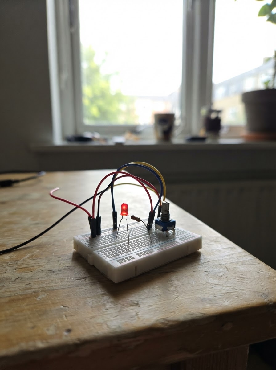
This project demonstrates analog input and PWM output on an Arduino Uno by building a simple LED dimmer controlled by a potentiometer. Turning the knob smoothly adjusts the LED brightness from off to full brightness, making it an ideal introduction to reading analog sensors and controlling power output.
The guide includes a complete wiring diagram, a parts list with the Arduino Uno, potentiometer, LED, and current-limiting resistor, step-by-step assembly instructions for breadboard layout, and ready-to-upload firmware that maps the potentiometer's analog reading to PWM brightness levels.
Wiring diagram

Gather all the parts
Assemble it in 4 steps
1. Prepare the breadboard power rails
Use jumper wires to connect the Arduino Uno 5V pin to the breadboard positive rail and an Arduino GND pin to the breadboard ground rail. All circuit ground connections must share this ground rail.
- Keep the red/positive and blue/ground rails consistent across the breadboard.
- The Uno can be powered through its USB port for this low-current circuit.
- Do not connect the 5V rail directly to Arduino analog pin A0 or digital pin D9.
2. Wire the 10 kΩ potentiometer
Place the potentiometer so its three terminals are in separate breadboard rows. Connect one outer terminal (End1) to the 5V rail, the opposite outer terminal (End2) to the GND rail, and the center terminal (wiper) to Arduino A0.
- If clockwise rotation makes the LED dim rather than brighten, swap the two outer potentiometer wires; leave the center wiper on A0.
- A0 is the Arduino pin labeled A0, not digital pin 0.
- Ensure the center wiper is not shorted to either power rail.
3. Install the LED and current-limiting resistor
Insert the LED with its long lead (anode) in one row and its short lead or flat-side lead (cathode) in a different row. Connect the cathode to the GND rail. Connect the LED anode to one end of the 220 Ω resistor, then connect the resistor’s other end to Arduino digital pin D9.
- D9 is PWM-capable, so it can vary LED brightness.
- The resistor may be placed on either side of the LED electrically, but it must remain in series with the LED.
- Never connect the LED directly from D9 to GND without the 220 Ω resistor; excessive current can damage the LED or Arduino pin.
- Check LED polarity before applying power.
4. Final connection check
Confirm the circuit has exactly these signal connections: potentiometer wiper to A0, D9 to 220 Ω resistor, resistor to LED anode, and LED cathode to GND. Confirm both outer potentiometer pins go to 5V and GND.
- After deploying the firmware, turn the potentiometer slowly: one direction should move from off to full brightness.
- Disconnect USB power before moving wires if you suspect a short circuit.
Review all connections
1. Connections between "potentiometer_1" and "Arduino"
2. Connections between "resistor_1" and "Arduino"
3. Connections between "led_1" and "Arduino"
Deploy the firmware
#include <Arduino.h>
// Potentiometer-controlled LED brightness for Arduino Uno.
// A0 reads 0..1023; D9 outputs PWM duty cycle 0..255.

const uint8_t POT_PIN = A0;
const uint8_t LED_PWM_PIN = 9;

int lastBrightness = -1;

void setup() {
  pinMode(LED_PWM_PIN, OUTPUT);
  analogWrite(LED_PWM_PIN, 0);
}

void loop() {
  const int potReading = analogRead(POT_PIN);
  const int brightness = map(potReading, 0, 1023, 0, 255);

  // Only update PWM when the requested visible brightness changes.
  if (brightness != lastBrightness) {
    analogWrite(LED_PWM_PIN, brightness);
    lastBrightness = brightness;
  }

  delay(10);
}
Remix this project
Make it yours in one click
Open a full copy of this project in your own Schematik workspace — diagram, code, parts, and assembly steps included. Swap the sensor, add features, or redesign the whole thing with AI. The author's original stays untouched.