Community project
Smart Mailbox Alert
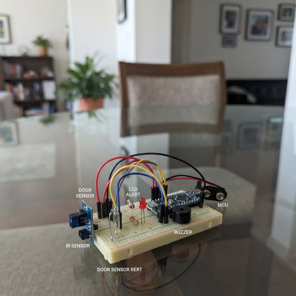
This smart mailbox alert system uses an ESP32 to monitor mail delivery and door status, alerting the homeowner when mail arrives or the mailbox is opened. The build combines an infrared reflective sensor to detect letters and a reed switch to sense the mailbox door, triggering an LED and buzzer with different alert patterns for each event.
This guide provides a complete parts list, wiring diagram, and step-by-step assembly instructions to integrate the sensors into a mailbox enclosure. The included firmware handles debouncing, manages alert timing, and distinguishes between mail detection and door-open events with distinct audio-visual feedback patterns.
Wiring diagram

Gather all the parts
Assemble it in 5 steps
1. Place the letter sensor
Mount ir_sensor inside the letter slot so a letter passes about 1–2 cm in front of its two small clear/dark sensor windows. Connect VCC to the ESP32 3V3 pin (power), GND to an ESP32 GND pin (ground), and DO to GPIO27 (letter-detected signal). Leave AO unconnected.
- Turn the small adjustment screw later until the DO indicator changes only when a letter passes the sensor.
- Do not connect the sensor to 5 V: its signal could then be too high for the ESP32 input.
2. Fit the magnetic door switch
Fix the magnet half to the mailbox door and the glass reed-switch half to the mailbox body so they are close together when the door is shut. Connect one door_reed wire (PIN1) to GPIO32 (door signal) and the other wire (PIN2) to ESP32 GND (ground).
- The two halves normally need to be within a few millimetres when the door is closed.
3. Wire the warning light
Put the 220 Ω led_resistor between GPIO26 and the long leg of status_led: resistor P1 goes to GPIO26 (light-control signal), and resistor P2 goes to the LED long leg, ANODE (limits current). Connect the LED short leg, GND, to an ESP32 GND pin (ground).
- Make sure the LED long and short legs are not swapped; reversed wiring will stop the light from working.
4. Wire the buzzer
Connect buzzer SIGNAL to GPIO25 (sound-control signal) and buzzer GND to an ESP32 GND pin (ground).
- If your buzzer has a + marking instead of SIGNAL, connect that marked pin to GPIO25.
5. Check and power the mailbox
Make sure every part that uses ground reaches an ESP32 GND pin, then plug the ESP32 into USB power. Keep the door closed while you set the infrared sensor screw so it notices a letter but not the mailbox wall.
- Keep the ESP32 and all low-voltage wiring dry and insulated inside the mailbox; water can short the board and damage it.
Review all connections
1. Connections between "ir_sensor" and "ESP32"
2. Connections between "door_reed" and "ESP32"
3. Connections between "buzzer" and "ESP32"
4. Connections between "led_resistor" and "ESP32"
5. Connections between "status_led" and "ESP32"
Deploy the firmware
// Smart mailbox notifier for an ESP32 DevKit v1.
// The TCRT5000 module output is normally HIGH and goes LOW when a letter is detected.
// The reed switch is closed while the magnet is nearby (door closed) and opens when the door opens.

#include <Arduino.h>

constexpr uint8_t IR_SENSOR_PIN = 27;
constexpr uint8_t DOOR_REED_PIN = 32;
constexpr uint8_t BUZZER_PIN = 25;
constexpr uint8_t LED_PIN = 26;

constexpr unsigned long ALERT_DURATION_MS = 10000;
constexpr unsigned long DOOR_BEEP_INTERVAL_MS = 500;
constexpr unsigned long DEBOUNCE_MS = 40;

enum AlertMode {
  NO_ALERT,
  MAIL_ALERT,
  DOOR_ALERT
};

AlertMode alertMode = NO_ALERT;
unsigned long alertStartedAt = 0;

bool lastIrReading = HIGH;
bool stableIrReading = HIGH;
unsigned long irChangedAt = 0;

bool lastDoorReading = HIGH;
bool stableDoorReading = HIGH;
unsigned long doorChangedAt = 0;

void startAlert(AlertMode newMode) {
  alertMode = newMode;
  alertStartedAt = millis();
}

void stopAlert() {
  alertMode = NO_ALERT;
  digitalWrite(LED_PIN, LOW);
  digitalWrite(BUZZER_PIN, LOW);
}

void updateAlertOutputs(unsigned long now) {
  if (alertMode == NO_ALERT) {
    digitalWrite(LED_PIN, LOW);
    digitalWrite(BUZZER_PIN, LOW);
    return;
  }

  if (now - alertStartedAt >= ALERT_DURATION_MS) {
    stopAlert();
    return;
  }

  digitalWrite(LED_PIN, HIGH);

  if (alertMode == MAIL_ALERT) {
    digitalWrite(BUZZER_PIN, HIGH);
  } else {
    bool beepOn = ((now - alertStartedAt) / DOOR_BEEP_INTERVAL_MS) % 2 == 0;
    digitalWrite(BUZZER_PIN, beepOn ? HIGH : LOW);
  }
}

void setup() {
  pinMode(IR_SENSOR_PIN, INPUT);
  pinMode(DOOR_REED_PIN, INPUT_PULLUP);
  pinMode(BUZZER_PIN, OUTPUT);
  pinMode(LED_PIN, OUTPUT);

  digitalWrite(BUZZER_PIN, LOW);
  digitalWrite(LED_PIN, LOW);

  // Start from the real sensor states so switching on the ESP32 does not create a false alert.
  lastIrReading = stableIrReading = digitalRead(IR_SENSOR_PIN);
  lastDoorReading = stableDoorReading = digitalRead(DOOR_REED_PIN);
}

void loop() {
  const unsigned long now = millis();

  bool irReading = digitalRead(IR_SENSOR_PIN);
  if (irReading != lastIrReading) {
    lastIrReading = irReading;
    irChangedAt = now;
  }
  if ((now - irChangedAt >= DEBOUNCE_MS) && irReading != stableIrReading) {
    stableIrReading = irReading;
    if (stableIrReading == LOW) {
      startAlert(MAIL_ALERT);
    }
  }

  bool doorReading = digitalRead(DOOR_REED_PIN);
  if (doorReading != lastDoorReading) {
    lastDoorReading = doorReading;
    doorChangedAt = now;
  }
  if ((now - doorChangedAt >= DEBOUNCE_MS) && doorReading != stableDoorReading) {
    stableDoorReading = doorReading;
    if (stableDoorReading == HIGH) {
      startAlert(DOOR_ALERT);
    }
  }

  updateAlertOutputs(now);
}
Remix this project
Make it yours in one click
Open a full copy of this project in your own Schematik workspace — diagram, code, parts, and assembly steps included. Swap the sensor, add features, or redesign the whole thing with AI. The author's original stays untouched.