Community project
Programmable ESP32 Display Cap
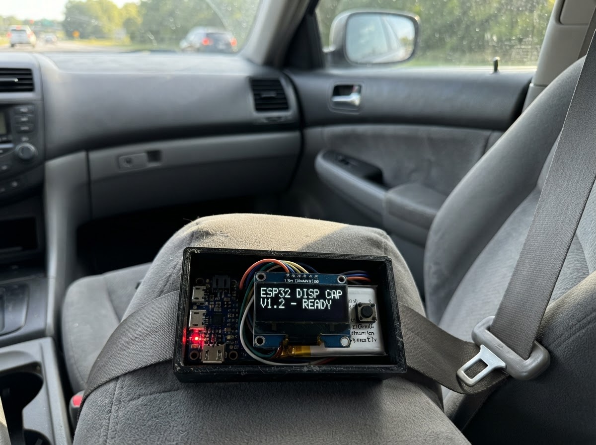
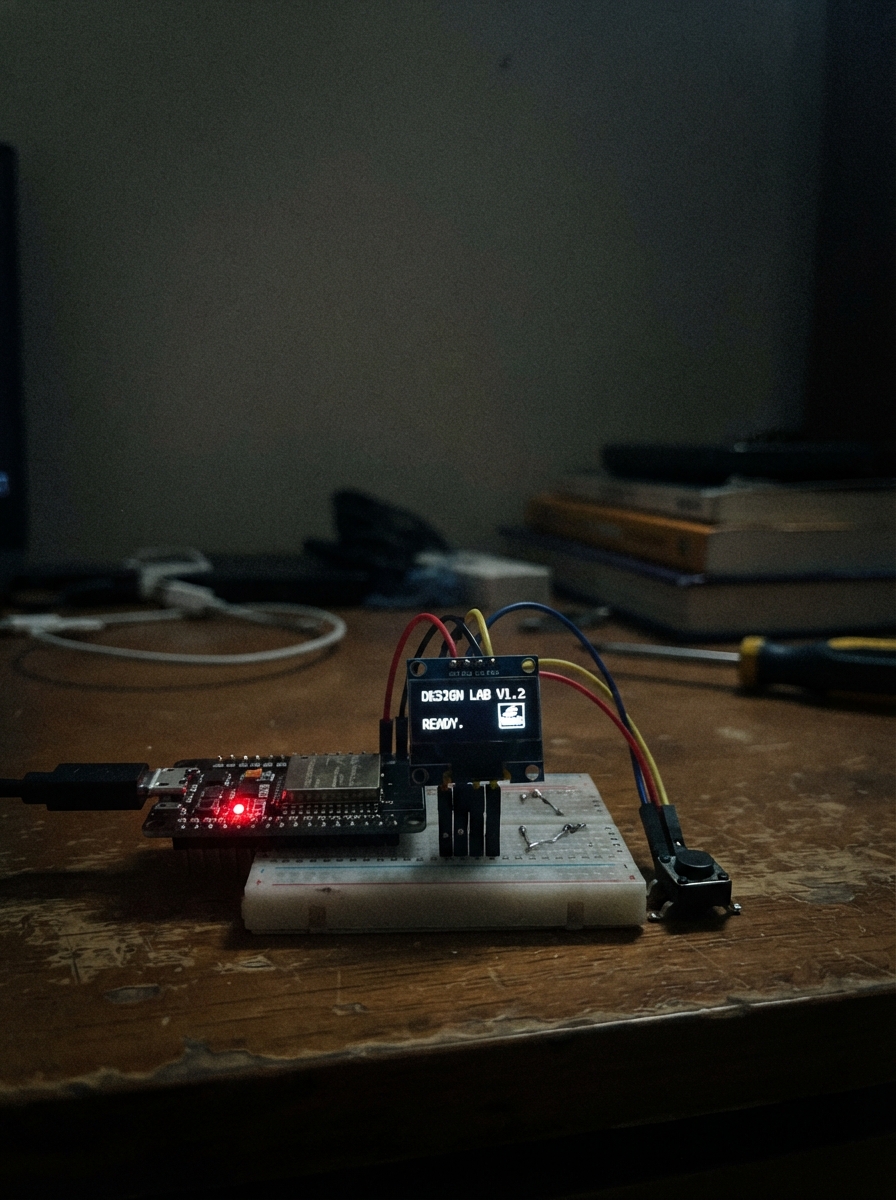
This programmable ESP32 display cap turns a baseball cap into a wearable message board. The project combines a 1.3-inch OLED screen mounted in the cap's front with two push buttons for cycling through custom text messages, all powered by a rechargeable lithium polymer battery with USB charging capability.
Builders will receive a complete wiring diagram showing how to connect the display via I2C to the ESP32, integrate the push buttons for message navigation, and wire up the PowerBoost charger for reliable battery management. The guide includes a full parts list, step-by-step assembly instructions for securing components inside the cap, and ready-to-upload firmware that handles button debouncing and message cycling.
Wiring diagram
Gather all the parts
Assemble it in 5 steps
1. Mount the screen in the cap front
Cut a neat rectangular window in the front panel of the cap, then secure display_1 behind it with thin double-sided foam tape or a small 3D-printed holder. Keep the glowing face toward the outside and leave its four connection pads accessible on the inside.
- Place a thin clear plastic cover over the opening if the screen could be bumped or exposed to sweat.
- Do not sew through the display board or press hard on the glass face — it can crack.
2. Connect the screen wires
Use flexible stranded wire: connect display_1 VCC to ESP32 3V3 (power), display_1 GND to ESP32 GND (ground), display_1 SDA to GPIO21 (data), and display_1 SCL to GPIO22 (data).
- Use short wires and add a dab of hot glue where each wire meets the display board so repeated bending does not pull it loose.
- Make sure VCC and GND are not swapped — swapped power can damage the screen.
3. Add the two message buttons
Put button_previous and button_next where your fingers can reach them under the brim. Connect one leg of button_previous to GPIO26 (signal) and its other leg to GND; connect one leg of button_next to GPIO27 (signal) and its other leg to GND.
- The buttons do not have a positive and negative side. Each quick press moves through the saved messages once.
4. Make the rechargeable power chain
Connect battery_1 BAT+ to power_manager_1 BAT (battery power) and battery_1 BAT- to power_manager_1 GND (battery ground). Connect power_manager_1 5V to the ESP32 VIN or 5V pin (power). The PowerBoost board’s own USB connector is the charging socket.
- Keep the battery and power board in a small fabric pocket or printed enclosure at the back of the cap to balance the screen’s weight.
- Do not puncture, crush, fold, or sew through the lithium battery — a damaged battery can overheat or catch fire.
- Only connect the PowerBoost 5V output to the ESP32 VIN or 5V pin, never to its 3V3 pin.
5. Insulate and secure everything
Cover every exposed solder joint with heat-shrink tube or electrical tape. Secure the ESP32, power_manager_1, and battery_1 so no board or wire can flex when you put the cap on. Leave the PowerBoost USB connector reachable for charging.
- Before putting the electronics in the cap, briefly power it on while it is on a table and confirm the screen shows text.
- Loose metal connections can short against each other, which can damage boards or make the battery hot.
Review all connections
1. Connections between "display_1" and "ESP32"
2. Connections between "button_next" and "ESP32"
3. Connections between "button_previous" and "ESP32"
4. Connections between "battery_1" and "ESP32"
5. Connections between "power_manager_1" and "ESP32"
Deploy the firmware
#include <Arduino.h>
#include <Wire.h>
#include <Adafruit_GFX.h>
#include <Adafruit_SSD1306.h>

constexpr int OLED_SDA_PIN = 21;
constexpr int OLED_SCL_PIN = 22;
constexpr int NEXT_BUTTON_PIN = 27;
constexpr int PREVIOUS_BUTTON_PIN = 26;
constexpr uint8_t SCREEN_WIDTH = 128;
constexpr uint8_t SCREEN_HEIGHT = 64;
constexpr uint8_t OLED_ADDRESS = 0x3C;
constexpr unsigned long DEBOUNCE_MS = 180;

Adafruit_SSD1306 display(SCREEN_WIDTH, SCREEN_HEIGHT, &Wire, -1);

const char *messages[] = {
  "HELLO!",
  "MAKE",
  "SOMETHING",
  "YOUR TEXT",
  "ESP32 CAP"
};
constexpr size_t MESSAGE_COUNT = sizeof(messages) / sizeof(messages[0]);
size_t messageIndex = 0;
unsigned long lastButtonTime = 0;

void drawMessage() {
  display.clearDisplay();
  display.setTextColor(SSD1306_WHITE);
  display.setTextWrap(true);
  display.setTextSize(1);
  display.setCursor(0, 2);
  display.println("PROGRAMMABLE CAP");
  display.drawFastHLine(0, 14, SCREEN_WIDTH, SSD1306_WHITE);

  display.setTextSize(2);
  display.setCursor(0, 27);
  display.println(messages[messageIndex]);

  display.setTextSize(1);
  display.setCursor(0, 55);
  display.print("< PREV       NEXT >");
  display.display();
}

bool pressed(int pin) {
  if (digitalRead(pin) != LOW) {
    return false;
  }
  const unsigned long now = millis();
  if (now - lastButtonTime < DEBOUNCE_MS) {
    return false;
  }
  lastButtonTime = now;
  return true;
}

void setup() {
  pinMode(NEXT_BUTTON_PIN, INPUT_PULLUP);
  pinMode(PREVIOUS_BUTTON_PIN, INPUT_PULLUP);

  Wire.begin(OLED_SDA_PIN, OLED_SCL_PIN);
  if (!display.begin(SSD1306_SWITCHCAPVCC, OLED_ADDRESS)) {
    while (true) {
      delay(1000);
    }
  }
  drawMessage();
}

void loop() {
  if (pressed(NEXT_BUTTON_PIN)) {
    messageIndex = (messageIndex + 1) % MESSAGE_COUNT;
    drawMessage();
  } else if (pressed(PREVIOUS_BUTTON_PIN)) {
    messageIndex = (messageIndex + MESSAGE_COUNT - 1) % MESSAGE_COUNT;
    drawMessage();
  }
  delay(10);
}
Remix this project
Make it yours in one click
Open a full copy of this project in your own Schematik workspace, diagram, code, parts, and assembly steps included. Swap the sensor, add features, or redesign the whole thing with AI. The author's original stays untouched.