Community project
Programmable Traffic Controller
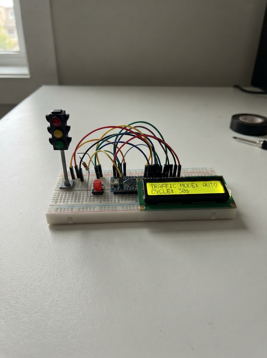
Build a programmable traffic controller that manages north–south and east–west traffic lights with customizable timing plans. This project uses an Arduino Uno to cycle through traffic phases, display status on an LCD screen, and let you switch between disabled, automatic, and manual modes via push buttons.
This guide provides a complete wiring diagram, parts list, and step-by-step assembly instructions. You'll learn how to wire dual traffic lights with current-limiting resistors, connect an I2C LCD display, integrate multiple push buttons with INPUT_PULLUP configuration, and upload firmware that stores timing plans in EEPROM so your traffic controller remembers settings between power cycles.
Wiring diagram

Gather all the parts
Assemble it in 7 steps
1. Place the traffic lights and resistors
Put the two traffic-light modules on the breadboard and label them north–south and east–west. Put six 220 Ω resistors nearby: one resistor is used in each red, yellow, and green lamp wire. The resistor can face either way around.
- Keep red at the top, yellow in the middle, and green at the bottom on both modules so the intersection is easy to read.
- Do not leave out the resistors when using separate LEDs — too much current can damage an LED or the Arduino pin. If your lamp modules already contain resistors, do not fit a second resistor; replace the six loose resistor connections with direct module connections instead.
2. Wire the north–south traffic light
Connect north_south_signal GND to Arduino GND (ground). Connect D2 to ns_red_resistor A, then ns_red_resistor B to north_south_signal RED (red-lamp signal). Connect D3 to ns_yellow_resistor A, then ns_yellow_resistor B to north_south_signal YELLOW (yellow-lamp signal). Connect D4 to ns_green_resistor A, then ns_green_resistor B to north_south_signal GREEN (green-lamp signal).
- A resistor has no positive or negative end, so either leg can be the Arduino side.
- Make sure the module GND wire goes to Arduino GND, not to 5V — swapped power can damage the module.
3. Wire the east–west traffic light
Connect east_west_signal GND to Arduino GND (ground). Connect D5 to ew_red_resistor A, then ew_red_resistor B to east_west_signal RED (red-lamp signal). Connect D6 to ew_yellow_resistor A, then ew_yellow_resistor B to east_west_signal YELLOW (yellow-lamp signal). Connect D7 to ew_green_resistor A, then ew_green_resistor B to east_west_signal GREEN (green-lamp signal).
- Both traffic lights may share the same Arduino GND rail.
- Do not connect any RED, YELLOW, or GREEN signal pin directly to 5V; those pins are controlled by the Arduino.
4. Add the mode buttons
For each existing mode button, connect its GND leg to Arduino GND (ground): Disabled SIGNAL to D8 (disabled-mode signal), Automatic SIGNAL to D9 (automatic-mode signal), and Manual SIGNAL to D10 (manual-mode signal).
- The program supplies the small pull-up resistors inside the Arduino, so no extra resistors are needed for these buttons.
- On a four-legged tactile button, use legs from opposite sides of the switch. If both wires use legs already joined on one side, the button will not work.
5. Wire the display
Connect settings_lcd VCC to Arduino 5V (power), GND to Arduino GND (ground), SDA to A4 (screen data), and SCL to A5 (screen timing).
- The display normally shows its address as 0x27 in the supplied design; this is the common address for this style of screen.
- Make sure VCC and GND are not swapped — swapped power can damage the screen.
6. Add the plan-setting buttons
Connect menu_up_button GND to Arduino GND and SIGNAL to D11 (increase a value). Connect menu_down_button GND to Arduino GND and SIGNAL to D12 (decrease a value). Connect menu_select_button GND to Arduino GND and SIGNAL to D13 (open the editor, move to the next setting, and save).
- Label these three buttons Up, Down, and Select/Save before testing.
- Keep each button’s two used legs on separate breadboard rows, otherwise pressing it cannot change the input.
7. Choose and save a traffic plan
Plug the Arduino into USB. The screen starts in automatic mode and shows plan 1. Tap Up or Down to choose plan 1, 2, or 3. Tap Select/Save to edit: Up and Down change the shown number of seconds, and Select/Save moves from green time to yellow time to the all-red safety time. After the third Select/Save press, that plan is saved inside the Arduino and remains saved after USB power is removed.
- Disabled gives flashing yellow in both directions. Automatic uses the chosen saved plan. Manual starts north–south green; each later Manual tap moves one safe stage forward.
- This is a low-voltage model only. Do not connect it to real road signals, mains wiring, or high-power lamps.
Review all connections
1. Connections between "north_south_signal" and "Arduino"
2. Connections between "east_west_signal" and "Arduino"
3. Connections between "disabled_button" and "Arduino"
4. Connections between "automatic_button" and "Arduino"
5. Connections between "manual_button" and "Arduino"
6. Connections between "settings_lcd" and "Arduino"
7. Connections between "menu_up_button" and "Arduino"
8. Connections between "menu_down_button" and "Arduino"
9. Connections between "menu_select_button" and "Arduino"
10. Connections between "ns_red_resistor" and "Arduino"
11. Connections between "ns_yellow_resistor" and "Arduino"
12. Connections between "ns_green_resistor" and "Arduino"
13. Connections between "ew_red_resistor" and "Arduino"
14. Connections between "ew_yellow_resistor" and "Arduino"
15. Connections between "ew_green_resistor" and "Arduino"
Deploy the firmware
#include <Arduino.h>
#include <EEPROM.h>
#include <LiquidCrystal_I2C.h>

// Buttons use INPUT_PULLUP: each button connects its input pin to GND when pressed.

// Hoisted type definitions
enum Mode { DISABLED, AUTOMATIC, MANUAL };

enum Phase { NS_GO, NS_CAUTION, ALL_STOP_AFTER_NS, EW_GO, EW_CAUTION, ALL_STOP_AFTER_EW };

struct TimingPlan {
  byte greenSeconds;
  byte yellowSeconds;
  byte allRedSeconds;
};


// Forward declarations
void setLights(bool nsRed, bool nsYellow, bool nsGreen, bool ewRed, bool ewYellow, bool ewGreen);
bool pressed(byte pin);
void loadPlans();
void saveSelectedPlan();
unsigned long currentPhaseLimit();
void showPhase();
void advancePhase();
void enterMode(Mode newMode);
void drawScreen();
void changeEditValue(int direction);
void handleMenu();

const byte NS_RED_PIN = 2;
const byte NS_YELLOW_PIN = 3;
const byte NS_GREEN_PIN = 4;
const byte EW_RED_PIN = 5;
const byte EW_YELLOW_PIN = 6;
const byte EW_GREEN_PIN = 7;
const byte DISABLED_BUTTON_PIN = 8;
const byte AUTOMATIC_BUTTON_PIN = 9;
const byte MANUAL_BUTTON_PIN = 10;
const byte MENU_UP_PIN = 11;
const byte MENU_DOWN_PIN = 12;
const byte MENU_SELECT_PIN = 13;

const unsigned long DISABLED_FLASH_MS = 500;
const unsigned long BUTTON_DEBOUNCE_MS = 180;
const byte PLAN_COUNT = 3;
const byte EEPROM_MAGIC = 0xA7;

LiquidCrystal_I2C lcd(0x27, 16, 2);


TimingPlan plans[PLAN_COUNT];
Mode mode = AUTOMATIC;
Phase phase = NS_GO;
byte selectedPlan = 0;
byte editField = 0; // 0 green, 1 yellow, 2 all-red
bool editing = false;
bool screenDirty = true;
unsigned long phaseStartedAt = 0;
unsigned long lastFlashAt = 0;
unsigned long lastButtonAt = 0;
bool flashOn = false;

void setLights(bool nsRed, bool nsYellow, bool nsGreen, bool ewRed, bool ewYellow, bool ewGreen) {
  digitalWrite(NS_RED_PIN, nsRed);
  digitalWrite(NS_YELLOW_PIN, nsYellow);
  digitalWrite(NS_GREEN_PIN, nsGreen);
  digitalWrite(EW_RED_PIN, ewRed);
  digitalWrite(EW_YELLOW_PIN, ewYellow);
  digitalWrite(EW_GREEN_PIN, ewGreen);
}

bool pressed(byte pin) {
  if (digitalRead(pin) == LOW && millis() - lastButtonAt >= BUTTON_DEBOUNCE_MS) {
    lastButtonAt = millis();
    return true;
  }
  return false;
}

void loadPlans() {
  if (EEPROM.read(0) != EEPROM_MAGIC) {
    plans[0] = {8, 2, 1};
    plans[1] = {15, 3, 2};
    plans[2] = {30, 4, 2};
    EEPROM.update(0, EEPROM_MAGIC);
    for (byte i = 0; i < PLAN_COUNT; i++) EEPROM.put(1 + i * sizeof(TimingPlan), plans[i]);
  } else {
    for (byte i = 0; i < PLAN_COUNT; i++) EEPROM.get(1 + i * sizeof(TimingPlan), plans[i]);
  }
}

void saveSelectedPlan() {
  EEPROM.put(1 + selectedPlan * sizeof(TimingPlan), plans[selectedPlan]);
}

unsigned long currentPhaseLimit() {
  TimingPlan &plan = plans[selectedPlan];
  if (phase == NS_CAUTION || phase == EW_CAUTION) return (unsigned long)plan.yellowSeconds * 1000UL;
  if (phase == ALL_STOP_AFTER_NS || phase == ALL_STOP_AFTER_EW) return (unsigned long)plan.allRedSeconds * 1000UL;
  return (unsigned long)plan.greenSeconds * 1000UL;
}

void showPhase() {
  switch (phase) {
    case NS_GO:             setLights(false, false, true,  true,  false, false); break;
    case NS_CAUTION:        setLights(false, true,  false, true,  false, false); break;
    case ALL_STOP_AFTER_NS: setLights(true,  false, false, true,  false, false); break;
    case EW_GO:             setLights(true,  false, false, false, false, true);  break;
    case EW_CAUTION:        setLights(true,  false, false, false, true,  false); break;
    case ALL_STOP_AFTER_EW: setLights(true,  false, false, true,  false, false); break;
  }
}

void advancePhase() {
  phase = (Phase)((phase + 1) % 6);
  phaseStartedAt = millis();
  showPhase();
  screenDirty = true;
}

void enterMode(Mode newMode) {
  mode = newMode;
  editing = false;
  if (mode == AUTOMATIC || mode == MANUAL) {
    phase = NS_GO;
    phaseStartedAt = millis();
    showPhase();
  } else {
    lastFlashAt = millis();
    flashOn = false;
    setLights(false, false, false, false, false, false);
  }
  screenDirty = true;
}

const char *modeName() {
  if (mode == DISABLED) return "DISABLED";
  if (mode == MANUAL) return "MANUAL";
  return "AUTO";
}

void drawScreen() {
  if (!screenDirty) return;
  screenDirty = false;
  lcd.setCursor(0, 0);
  if (editing) {
    lcd.print("EDIT P");
    lcd.print(selectedPlan + 1);
    lcd.print(" ");
    if (editField == 0) lcd.print("GREEN   ");
    else if (editField == 1) lcd.print("YELLOW  ");
    else lcd.print("ALL RED ");
    lcd.setCursor(0, 1);
    byte value = editField == 0 ? plans[selectedPlan].greenSeconds : (editField == 1 ? plans[selectedPlan].yellowSeconds : plans[selectedPlan].allRedSeconds);
    lcd.print("UP/DN ");
    lcd.print(value);
    lcd.print(" sec     ");
  } else {
    lcd.print(modeName());
    lcd.print(" P");
    lcd.print(selectedPlan + 1);
    lcd.print("          ");
    lcd.setCursor(0, 1);
    lcd.print("G"); lcd.print(plans[selectedPlan].greenSeconds);
    lcd.print(" Y"); lcd.print(plans[selectedPlan].yellowSeconds);
    lcd.print(" R"); lcd.print(plans[selectedPlan].allRedSeconds);
    lcd.print("s UP/DN ");
  }
}

void changeEditValue(int direction) {
  byte *value = editField == 0 ? &plans[selectedPlan].greenSeconds : (editField == 1 ? &plans[selectedPlan].yellowSeconds : &plans[selectedPlan].allRedSeconds);
  byte minimum = editField == 0 ? 3 : 1;
  byte maximum = editField == 0 ? 99 : 20;
  int next = (int)*value + direction;
  if (next >= minimum && next <= maximum) *value = (byte)next;
  screenDirty = true;
}

void handleMenu() {
  if (editing) {
    if (pressed(MENU_UP_PIN)) changeEditValue(1);
    else if (pressed(MENU_DOWN_PIN)) changeEditValue(-1);
    else if (pressed(MENU_SELECT_PIN)) {
      editField++;
      if (editField >= 3) {
        saveSelectedPlan();
        editing = false;
        editField = 0;
      }
      screenDirty = true;
    }
  } else {
    if (pressed(MENU_UP_PIN)) {
      selectedPlan = (selectedPlan + PLAN_COUNT - 1) % PLAN_COUNT;
      screenDirty = true;
    } else if (pressed(MENU_DOWN_PIN)) {
      selectedPlan = (selectedPlan + 1) % PLAN_COUNT;
      screenDirty = true;
    } else if (pressed(MENU_SELECT_PIN)) {
      editing = true;
      editField = 0;
      screenDirty = true;
    }
  }
}

void setup() {
  pinMode(NS_RED_PIN, OUTPUT); pinMode(NS_YELLOW_PIN, OUTPUT); pinMode(NS_GREEN_PIN, OUTPUT);
  pinMode(EW_RED_PIN, OUTPUT); pinMode(EW_YELLOW_PIN, OUTPUT); pinMode(EW_GREEN_PIN, OUTPUT);
  pinMode(DISABLED_BUTTON_PIN, INPUT_PULLUP); pinMode(AUTOMATIC_BUTTON_PIN, INPUT_PULLUP); pinMode(MANUAL_BUTTON_PIN, INPUT_PULLUP);
  pinMode(MENU_UP_PIN, INPUT_PULLUP); pinMode(MENU_DOWN_PIN, INPUT_PULLUP); pinMode(MENU_SELECT_PIN, INPUT_PULLUP);
  loadPlans();
  lcd.init();
  lcd.backlight();
  enterMode(AUTOMATIC);
}

void loop() {
  // Mode buttons take priority and always close the settings menu.
  if (pressed(DISABLED_BUTTON_PIN)) enterMode(DISABLED);
  else if (pressed(AUTOMATIC_BUTTON_PIN)) enterMode(AUTOMATIC);
  else if (pressed(MANUAL_BUTTON_PIN)) {
    if (mode != MANUAL) enterMode(MANUAL);
    else advancePhase();
  } else handleMenu();

  if (mode == DISABLED && millis() - lastFlashAt >= DISABLED_FLASH_MS) {
    lastFlashAt = millis();
    flashOn = !flashOn;
    setLights(false, flashOn, false, false, flashOn, false);
  }
  if (mode == AUTOMATIC && millis() - phaseStartedAt >= currentPhaseLimit()) advancePhase();
  drawScreen();
}
Remix this project
Make it yours in one click
Open a full copy of this project in your own Schematik workspace — diagram, code, parts, and assembly steps included. Swap the sensor, add features, or redesign the whole thing with AI. The author's original stays untouched.