Community project
光线变化报警器
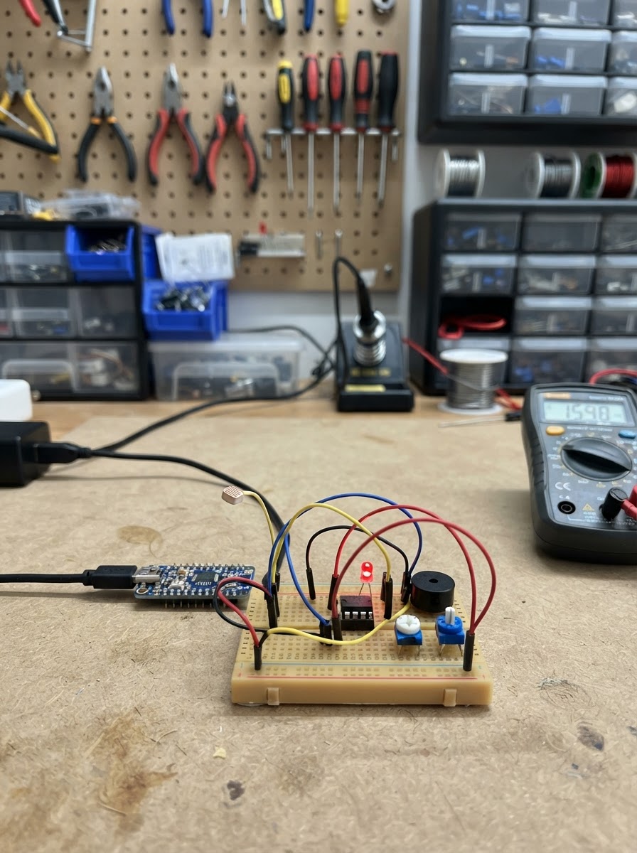
This light change alarm detects sudden shifts in ambient brightness and triggers an alert. Built around an LM358 operational amplifier and a photoresistor, the circuit continuously monitors light levels and compares them against a user-adjustable threshold using analog electronics—no microcontroller code required.
The guide provides a complete wiring diagram, parts list, and step-by-step assembly instructions for connecting the photoresistor input stage, the LM358 amplifier, the comparison circuit, and the LED and buzzer outputs. Once powered via USB-C, the system can be calibrated with the potentiometer to trigger alarms at desired light thresholds.
Wiring diagram

Gather all the parts
Assemble it in 5 steps
1. 准备 USB-C 5 V 电源
使用明确标注为“USB-C 5 V sink / 带 CC 电阻”的电源输出小板。将其 VBUS 接为全电路 +5 V 母线,GND 接为全电路公共地。不要把 Type-C 母座的 CC 引脚悬空或自行短接;应使用带两个 5.1 kΩ CC 下拉电阻的成品小板。
- 先不插入 USB-C 电源,用万用表确认 VBUS 与 GND 没有短路。
- 所有器件的地必须接到同一条 GND 母线。
- 仅接 5 V USB 电源;不要接 9 V/12 V 快充触发板输出。
2. 搭建光敏输入与 LM358 放大器
将 ldr_1 的一端接 +5 V,另一端作为 SENSE 节点。SENSE 接 LM358 的 3 脚(IN+ A)。在 SENSE 与 GND 间接 100 kΩ 电阻。LM358 的 2 脚(IN− A)经 10 kΩ 电阻接 GND;再从 1 脚(OUT A)经 100 kΩ 电阻反馈到 2 脚,形成约 11 倍非反相增益。LM358 的 8 脚接 +5 V、4 脚接 GND。
- DIP-8 芯片缺口朝上时,从左上角起逆时针数脚;LM358 的 A 通道是 1、2、3 脚。
- 在 LM358 的 8 脚与 4 脚之间、靠近芯片处并联 100 nF 陶瓷去耦电容。
- 不要把 LM358 的 1、2、3 脚与 LM393 的相同脚号混淆。
3. 接好 LM393 阈值比较器
将 LM358 的 1 脚输出接 LM393 的 3 脚(IN+ A)。threshold_pot_1 的两端分别接 +5 V 与 GND,中心滑动端接 LM393 的 2 脚(IN− A)。LM393 的 8 脚接 +5 V、4 脚接 GND。未使用的第二比较器:5 脚和 6 脚都接 GND,7 脚悬空。LM393 的 1 脚是开集电极报警输出 ALARM。
- 顺时针或逆时针转动阈值电位器会改变触发亮度;最终以实际测试方向为准。
- LM393 的 8 脚与 4 脚之间也要就近放置一个 100 nF 去耦电容。
- LM393 的 1 脚只能拉低,不能像推挽输出那样直接提供正电流。
4. 连接 LED 与有源蜂鸣器
alarm_led_1 的阳极必须先串联 1 kΩ 电阻后接 +5 V,阴极接 ALARM(LM393 1 脚)。buzzer_1 必须选 5 V、工作电流不超过 10 mA 的有源蜂鸣器:其“+”脚接 +5 V,“−”脚接同一 ALARM 节点。这样 LM393 在触发时拉低 ALARM,LED 和蜂鸣器同时工作。
- LED 长脚通常为阳极;若不亮,先断电再反接 LED。
- 蜂鸣器外壳或引脚上的“+”标记必须接 +5 V。
- 蜂鸣器额定电流若超过 10 mA,不能直接接 LM393;必须增加 NPN/MOSFET 驱动级。
- LED 必须保留 1 kΩ 串联电阻,不能直接接 5 V。
5. 上电与校准
再次检查 +5 V/GND 极性和芯片方向后插入 USB-C 电源。让传感器处于希望触发的环境亮度,缓慢旋转 threshold_pot_1,直到 LED 和蜂鸣器刚好切换;再略微回调以留出余量。用手遮住或照亮 ldr_1 验证报警方向。
- 本设计默认“光线增强时报警”,因为 LDR 接在分压器上臂;若要“变暗时报警”,将 LDR 与 100 kΩ 分压电阻的位置对调,且重新校准。
- 调试时避免让 USB-C 金属外壳或裸线碰到面包板导线,防止短路。
Review all connections
1. Connections between "usb_c_5v_1" and "Arduino"
2. Connections between "ldr_1" and "Arduino"
3. Connections between "lm358_1" and "Arduino"
4. Connections between "lm393_1" and "Arduino"
5. Connections between "threshold_pot_1" and "Arduino"
6. Connections between "alarm_led_1" and "Arduino"
7. Connections between "buzzer_1" and "Arduino"
Deploy the firmware
// This project is an entirely analog alarm circuit.
// LM358 and LM393 perform sensing and comparison in hardware.
// No microcontroller I/O or firmware is used.
void setup() {}
void loop() {}
Remix this project
Make it yours in one click
Open a full copy of this project in your own Schematik workspace — diagram, code, parts, and assembly steps included. Swap the sensor, add features, or redesign the whole thing with AI. The author's original stays untouched.