Community project
Pulse Oximeter Wristband
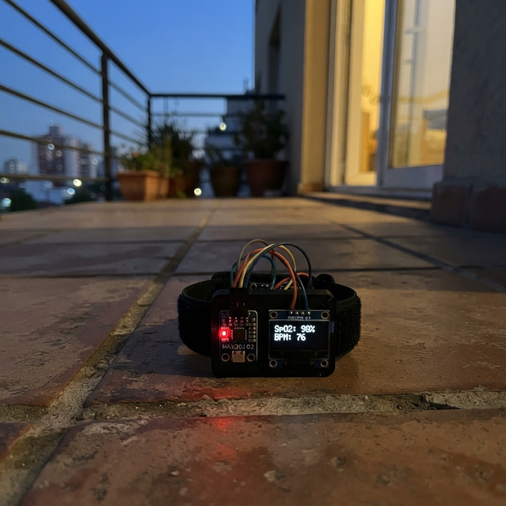
This pulse oximeter wristband uses an ESP32 microcontroller to measure heart rate by detecting blood flow through the fingertip. The MAX30102 optical sensor captures light reflections from blood vessels, while an SSD1306 OLED display shows real-time beats per minute readings on the wrist.
The guide provides a complete wiring diagram, parts list, and step-by-step assembly instructions to build a functional wearable heart rate monitor. Pre-written firmware handles sensor initialization, heart rate calculation, and display updates, so the device is ready to use after assembly and testing.
Wiring diagram

Gather all the parts
Assemble it in 4 steps
1. Keep power off while wiring
Leave the NodeMCU unplugged from USB while you make the connections. Put the MAX30102 and OLED where their printed pin labels can be read.
- Use short jumper wires; loose wires can make the pulse number jump or make the screen stay blank.
- Do not connect either module to the NodeMCU 5V/VIN pin — the ESP8266 uses 3.3V signals and 5V can damage a 3.3V-only module.
2. Connect the MAX30102 pulse sensor
Connect MAX30102 VCC to NodeMCU 3V3 (power), MAX30102 GND to NodeMCU GND (ground), MAX30102 SDA to NodeMCU D2/GPIO4 (data), and MAX30102 SCL to NodeMCU D1/GPIO5 (clock). Leave the MAX30102 INT pin unconnected.
- The sensor's LED and detector window must face the skin. For a first test, hold a fingertip gently and steadily over it.
- Make sure VCC and GND are not swapped — swapped power can damage the sensor.
3. Connect the small OLED screen
Connect OLED VCC to NodeMCU 3V3 (power), OLED GND to NodeMCU GND (ground), OLED SDA to NodeMCU D2/GPIO4 (data), and OLED SCL to NodeMCU D1/GPIO5 (clock). These two data wires are deliberately shared with the MAX30102.
- If your OLED has several GND or VCC labels, use the pins marked for I2C; the common 0.96-inch four-pin screen is VCC, GND, SCL, SDA.
- Make sure VCC and GND are not swapped — swapped power can damage the screen.
4. Test the wrist-band reading
Secure the sensor so its window rests flat against skin without squeezing hard. Plug the NodeMCU into USB after checking every wire, then use Schematik’s Deploy button to load the project. The screen asks for a finger until the sensor sees enough reflected light, then shows the filtered heart rate in BPM.
- Keep still for about 10 seconds so the reading settles. A dark strap or foam ring around the sensor helps block room light.
- This is a hobby heart-rate display, not a medical device; do not use it to make medical decisions.
Review all connections
1. Connections between "max30102_1" and "ESP32"
2. Connections between "oled_1" and "ESP32"
Deploy the firmware
#include <Arduino.h>
#include <Wire.h>
#include <Adafruit_GFX.h>
#include <Adafruit_SSD1306.h>
#include <MAX30105.h>
#include "heartRate.h"


// Forward declarations
void showNoFinger();
void showPulse(int bpm);

constexpr uint8_t I2C_SDA_PIN = 4;  // NodeMCU D2
constexpr uint8_t I2C_SCL_PIN = 5;  // NodeMCU D1
constexpr uint8_t OLED_ADDRESS = 0x3C;
constexpr uint8_t SCREEN_WIDTH = 128;
constexpr uint8_t SCREEN_HEIGHT = 64;
constexpr long FINGER_THRESHOLD = 50000;
constexpr uint32_t DISPLAY_INTERVAL_MS = 250;

Adafruit_SSD1306 display(SCREEN_WIDTH, SCREEN_HEIGHT, &Wire, -1);
MAX30105 pulseSensor;

long lastBeatMs = 0;
float beatsPerMinute = 0.0F;
int displayedBpm = -1;
bool fingerPresent = false;
bool displayAvailable = false;
uint32_t lastDisplayMs = 0;

void showNoFinger() {
  display.clearDisplay();
  display.setTextColor(SSD1306_WHITE);
  display.setTextSize(1);
  display.setCursor(17, 10);
  display.println(F("PULSE WRIST BAND"));
  display.setCursor(12, 34);
  display.println(F("Place finger on"));
  display.setCursor(20, 47);
  display.println(F("MAX30102 sensor"));
  display.display();
}

void showPulse(int bpm) {
  display.clearDisplay();
  display.setTextColor(SSD1306_WHITE);
  display.setTextSize(1);
  display.setCursor(25, 5);
  display.println(F("HEART RATE"));
  display.setTextSize(4);
  display.setCursor(28, 22);
  display.print(bpm);
  display.setTextSize(1);
  display.setCursor(101, 47);
  display.print(F("BPM"));
  display.display();
}

void setup() {
  Wire.begin(I2C_SDA_PIN, I2C_SCL_PIN);

  displayAvailable = display.begin(SSD1306_SWITCHCAPVCC, OLED_ADDRESS);
  if (displayAvailable) {
    showNoFinger();
  }

  if (!pulseSensor.begin(Wire, I2C_SPEED_STANDARD)) {
    if (displayAvailable) {
      display.clearDisplay();
      display.setTextSize(1);
      display.setTextColor(SSD1306_WHITE);
      display.setCursor(8, 26);
      display.println(F("MAX30102 not found"));
      display.display();
    }
    while (true) {
      delay(1000);
    }
  }

  pulseSensor.setup();
  pulseSensor.setPulseAmplitudeRed(0x1F);
  pulseSensor.setPulseAmplitudeIR(0x1F);
  pulseSensor.setPulseAmplitudeGreen(0);
}

void loop() {
  const long irValue = pulseSensor.getIR();
  const bool nowFingerPresent = irValue > FINGER_THRESHOLD;

  if (!nowFingerPresent) {
    beatsPerMinute = 0.0F;
    displayedBpm = -1;
    if (fingerPresent && displayAvailable) {
      showNoFinger();
    }
    fingerPresent = false;
    delay(20);
    return;
  }

  if (!fingerPresent && displayAvailable) {
    showPulse(0);
  }
  fingerPresent = true;

  if (checkForBeat(irValue)) {
    const long now = millis();
    const long elapsed = now - lastBeatMs;
    lastBeatMs = now;

    if (elapsed > 0) {
      const float instantBpm = 60.0F / (elapsed / 1000.0F);
      if (instantBpm >= 35.0F && instantBpm <= 220.0F) {
        beatsPerMinute = beatsPerMinute == 0.0F ? instantBpm : (0.7F * beatsPerMinute + 0.3F * instantBpm);
      }
    }
  }

  const int roundedBpm = beatsPerMinute > 0.0F ? static_cast<int>(beatsPerMinute + 0.5F) : 0;
  if (displayAvailable && roundedBpm != displayedBpm && millis() - lastDisplayMs >= DISPLAY_INTERVAL_MS) {
    showPulse(roundedBpm);
    displayedBpm = roundedBpm;
    lastDisplayMs = millis();
  }

  delay(10);
}
Remix this project
Make it yours in one click
Open a full copy of this project in your own Schematik workspace — diagram, code, parts, and assembly steps included. Swap the sensor, add features, or redesign the whole thing with AI. The author's original stays untouched.
Related projects

Create A Complete Electrical Schematic Esp32 Sma
ESP32 · September 17, 2026Ayansh Agrawal
ESP32 Kare Ekran Projeleri
ESP32 · September 16, 2026Seref Ai
Component Qty --------------------------- ------
ESP32 · September 16, 2026Yathartha Chakrawal