Community project
Push Button LED Control
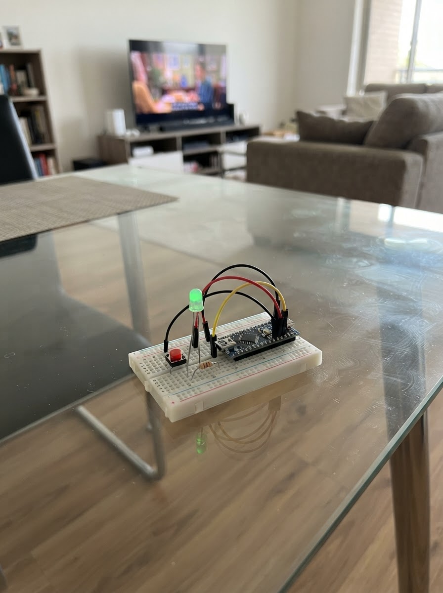
This project demonstrates basic digital input and output by wiring a push button to control an external LED on an Arduino Uno. When the button is pressed, the LED lights up; when released, it turns off. The guide includes a complete wiring diagram, parts list, and step-by-step assembly instructions for connecting the button and LED to the microcontroller.
Builders will learn fundamental Arduino concepts including pinMode configuration, digitalRead for sensing button states, and digitalWrite for controlling outputs. The included firmware uses INPUT_PULLUP to simplify wiring and shows how to map physical button presses to LED behavior in a simple control loop.
Wiring diagram

Gather all the parts
Assemble it in 4 steps
1. Make a common ground rail
Connect one Arduino Uno GND pin to the breadboard's blue/negative rail with a jumper wire. This rail is the shared return path for the LED and push button.
- Use a single continuous breadboard rail for both ground connections.
- Do not connect the ground rail to the Uno 5V pin.
2. Install and wire the external LED
Place the LED on the breadboard with its two leads in different rows. Connect the short lead (flat side/cathode) to the ground rail. Connect the long lead (anode) through a 220 Ω resistor to Uno digital pin D8.
- A 220 Ω resistor is normally red-red-brown with a gold tolerance band.
- The resistor may go on either side of the LED as long as it remains in series.
- The resistor is required; do not connect the LED directly between D8 and ground.
- Reverse the LED if it does not light when the button is held.
3. Install and wire the push button
Place the four-leg tactile button so it straddles the breadboard center gap. Connect one switched side of the button to the ground rail and the opposite switched side to Uno digital pin D2. No external pull-up or pull-down resistor is used.
- Pins on the same side of a typical four-leg button are internally connected; use one pin from each opposite side.
- The sketch enables D2's internal pull-up resistor, so it reads HIGH released and LOW when pressed.
- If the LED stays on or never turns on, rotate the button 90 degrees or verify that D2 and ground are connected to opposite switch sides.
4. Power the Uno and test
Connect the Uno to USB. With the button released, the external LED should be off. Hold the button down and the LED should light; release it and it should turn off.
- Use Schematik's Deploy button to compile and flash the saved sketch.
- Disconnect USB before moving wires if you suspect a short circuit.
Review all connections
1. Connections between "led_1" and "Arduino"
2. Connections between "button_1" and "Arduino"
Deploy the firmware
#include <Arduino.h>
// External LED follows a momentary push button.
// INPUT_PULLUP makes the input HIGH when released and LOW when pressed.

const uint8_t BUTTON_PIN = 2;
const uint8_t LED_PIN = 8;

void setup() {
  pinMode(LED_PIN, OUTPUT);
  pinMode(BUTTON_PIN, INPUT_PULLUP);
  digitalWrite(LED_PIN, LOW);
}

void loop() {
  bool buttonPressed = (digitalRead(BUTTON_PIN) == LOW);
  digitalWrite(LED_PIN, buttonPressed ? HIGH : LOW);
}
Remix this project
Make it yours in one click
Open a full copy of this project in your own Schematik workspace — diagram, code, parts, and assembly steps included. Swap the sensor, add features, or redesign the whole thing with AI. The author's original stays untouched.