Community project
Quitzone With Esp32
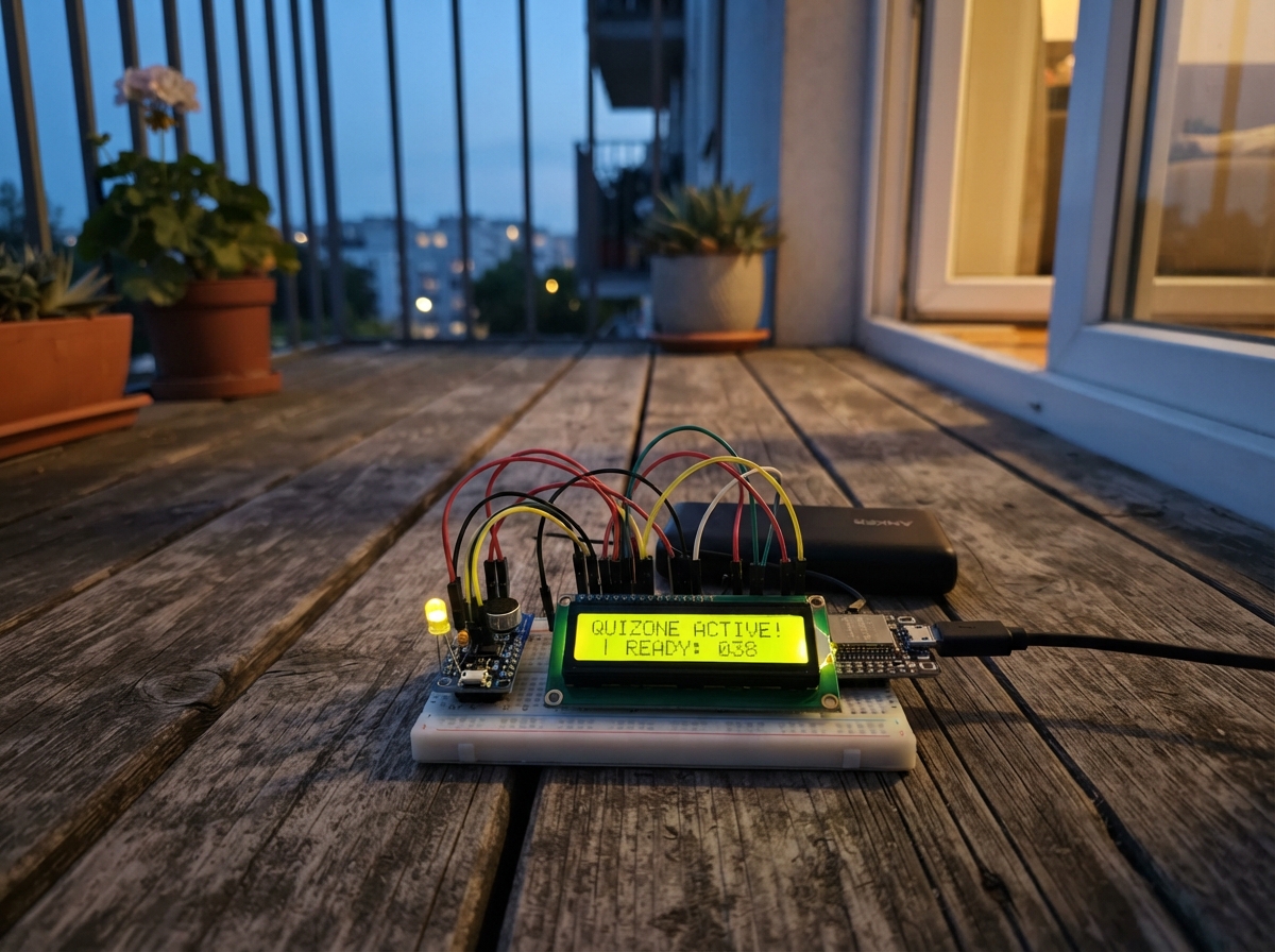
Quitzone is a sound-level monitor that helps identify noise conditions in a room using visual feedback. The ESP32 reads ambient sound through a KY-038 microphone module, categorizes the noise into three levels (normal, medium, high), and displays the result on an LCD screen with corresponding LED indicators—green for quiet, yellow for moderate, and red for loud environments.
This guide provides a complete wiring diagram, parts list, and Arduino firmware to build your own sound monitor. The assembly involves connecting the microphone and LEDs directly to the ESP32, routing the LCD display through a logic level converter for safe I2C communication, and uploading the sketch that continuously samples sound and updates the display. Thresholds are adjustable in the firmware so you can calibrate the device for your specific space.
Wiring diagram

Gather all the parts
Assemble it in 6 steps
1. Place the ESP32 and microphone module
Put the ESP32 DevKit v1 and KY-038 sound sensor where the microphone can hear the room. Connect the sensor VCC pin to ESP32 3V3 (power), sensor GND to ESP32 GND (ground), and sensor AO to GPIO34 (sound signal). Leave the sensor DO pin unconnected because this project measures the changing sound level from AO.
- Keep the microphone away from the three LEDs while testing so it responds to room sound rather than handling noise.
- Do not connect the sensor AO pin to 5V; GPIO34 is an ESP32 input and must receive no more than 3.3V.
2. Wire the green normal-level LED
Connect GPIO13 to one end of resistor_1, then connect the other end of resistor_1 to the long leg of led_1. Connect the short leg of led_1 to GND. The resistor limits current so the LED and ESP32 pin are protected.
- The long LED leg is positive; the short leg, usually beside the flat edge, goes to GND.
- Do not connect an LED directly between a GPIO pin and GND; without its 220 Ω resistor it can be damaged.
3. Wire the yellow medium-level LED
Connect GPIO14 to one end of resistor_2, then connect the other end of resistor_2 to the long leg of led_2. Connect the short leg of led_2 to GND. This LED lights for medium room noise.
- Make sure the LED direction is correct; reversing it prevents it from lighting.
4. Wire the red high-level LED
Connect GPIO18 to one end of resistor_3, then connect the other end of resistor_3 to the long leg of led_3. Connect the short leg of led_3 to GND. This LED lights when the room is loud.
- Each LED needs its own resistor; do not share one resistor between the LEDs.
5. Connect the LCD through the level converter
Connect lcd_1 VCC to ESP32 5V (power) and lcd_1 GND to ESP32 GND (ground). On level_shifter_1, connect LV to 3V3, HV to 5V, and GND to GND. Connect GPIO21 to LV1 (LCD data signal), GPIO22 to LV2 (LCD clock signal), LCD SDA to HV1, and LCD SCL to HV2.
- The level converter is the small board between the ESP32 and LCD data wires; it makes the LCD's 5V signals safe for the ESP32.
- Do not connect the LCD SDA or SCL wires straight to the ESP32 while the LCD is powered from 5V; 5V data signals can damage the ESP32.
6. Power up and adjust the sound levels
Plug the ESP32 into USB. The LCD shows a sound number and NORMAL, MEDIUM, or HIGH. In a quiet room it should show NORMAL and the green LED should light; make ordinary noise for MEDIUM and clap near the sensor for HIGH. If needed, turn the small adjustment screw on the KY-038 slowly, then observe the LCD again.
- The displayed sound number helps you choose better thresholds later if your room is unusually quiet or noisy.
- Keep fingers and metal tools away from the powered wiring while turning the sensor's adjustment screw.
Review all connections
1. Connections between "sound_sensor_1" and "ESP32"
2. Connections between "resistor_1" and "ESP32"
3. Connections between "led_1" and "ESP32"
4. Connections between "resistor_2" and "ESP32"
5. Connections between "led_2" and "ESP32"
6. Connections between "resistor_3" and "ESP32"
7. Connections between "led_3" and "ESP32"
8. Connections between "lcd_1" and "ESP32"
9. Connections between "level_shifter_1" and "ESP32"
Deploy the firmware
#include <Arduino.h>
#include <Wire.h>
#include <LiquidCrystal_I2C.h>


// Forward declarations
int readSoundLevel();
String levelForReading(int reading);
void setLevelLights(const String &level);
void showReading(int reading, const String &level);

constexpr uint8_t SOUND_PIN = 34;
constexpr uint8_t GREEN_LED_PIN = 13;
constexpr uint8_t YELLOW_LED_PIN = 14;
constexpr uint8_t RED_LED_PIN = 18;
constexpr uint8_t I2C_SDA_PIN = 21;
constexpr uint8_t I2C_SCL_PIN = 22;
constexpr uint8_t LCD_ADDRESS = 0x27;

// Adjust these after observing the displayed number in the intended room.
constexpr int MEDIUM_THRESHOLD = 55;
constexpr int HIGH_THRESHOLD = 140;
constexpr unsigned long UPDATE_INTERVAL_MS = 300;

LiquidCrystal_I2C lcd(LCD_ADDRESS, 16, 2);

int previousReading = -1;
String previousLevel = "";
unsigned long lastUpdate = 0;

int readSoundLevel() {
  const int sampleCount = 180;
  long total = 0;

  for (int i = 0; i < sampleCount; ++i) {
    total += analogRead(SOUND_PIN);
    delayMicroseconds(100);
  }

  const int average = total / sampleCount;
  long deviationTotal = 0;
  for (int i = 0; i < sampleCount; ++i) {
    deviationTotal += abs(analogRead(SOUND_PIN) - average);
    delayMicroseconds(100);
  }

  return deviationTotal / sampleCount;
}

String levelForReading(int reading) {
  if (reading >= HIGH_THRESHOLD) return "HIGH";
  if (reading >= MEDIUM_THRESHOLD) return "MEDIUM";
  return "NORMAL";
}

void setLevelLights(const String &level) {
  digitalWrite(GREEN_LED_PIN, level == "NORMAL" ? HIGH : LOW);
  digitalWrite(YELLOW_LED_PIN, level == "MEDIUM" ? HIGH : LOW);
  digitalWrite(RED_LED_PIN, level == "HIGH" ? HIGH : LOW);
}

void showReading(int reading, const String &level) {
  if (reading == previousReading && level == previousLevel) return;

  lcd.setCursor(0, 0);
  lcd.print("Sound:          ");
  lcd.setCursor(7, 0);
  lcd.print(reading);

  lcd.setCursor(0, 1);
  lcd.print("Level:          ");
  lcd.setCursor(7, 1);
  lcd.print(level);

  previousReading = reading;
  previousLevel = level;
}

void setup() {
  pinMode(GREEN_LED_PIN, OUTPUT);
  pinMode(YELLOW_LED_PIN, OUTPUT);
  pinMode(RED_LED_PIN, OUTPUT);
  analogReadResolution(12);

  Wire.begin(I2C_SDA_PIN, I2C_SCL_PIN);
  lcd.init();
  lcd.backlight();
  lcd.setCursor(0, 0);
  lcd.print("Sound monitor");
  lcd.setCursor(0, 1);
  lcd.print("Starting...");
  delay(800);
}

void loop() {
  const unsigned long now = millis();
  if (now - lastUpdate < UPDATE_INTERVAL_MS) return;
  lastUpdate = now;

  const int reading = readSoundLevel();
  const String level = levelForReading(reading);
  setLevelLights(level);
  showReading(reading, level);
}
Remix this project
Make it yours in one click
Open a full copy of this project in your own Schematik workspace — diagram, code, parts, and assembly steps included. Swap the sensor, add features, or redesign the whole thing with AI. The author's original stays untouched.