Community project
Retractable Cyberpunk Fitness Tracker
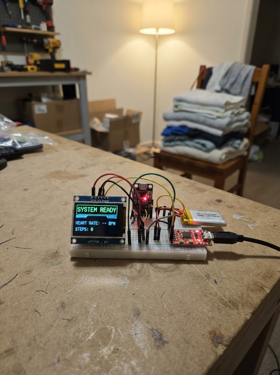
This retractable cyberpunk fitness tracker combines an ESP32 microcontroller with a MAX30102 pulse oximeter sensor and a 1.8-inch TFT display to monitor heart rate and blood oxygen levels in real time. The sensor mounts on a motorized retractable lead, styled after a neural-jack interface, while the display renders vital signs in a cyberpunk aesthetic with matrix-green text and scan-line effects.
This guide provides a complete parts list, wiring diagram, 3D-printed spool assembly instructions, and Arduino firmware to get the tracker running. Builders will learn how to integrate the TP4056 charger and boost converter for reliable battery power, configure SPI communication with the display, and read sensor data via I2C to display real-time biometric feedback.
Wiring diagram

Gather all the parts
Assemble it in 9 steps
1. Power chain — TP4056 charger
The TP4056 module is the charging brain. Identify its 6 pads: IN+, IN-, B+, B-, OUT+, OUT-. Leave it unplugged from USB for now. This module accepts any TP4056 board with USB-C or Micro-USB input.
- Look for 'USBC' or 'TYPE-C' silk text near the USB socket on the module.
- Do NOT connect USB until the battery and boost converter are fully wired.
2. Wire the battery to the TP4056
Connect the LiPo battery's JST-PH plug into the TP4056. The BAT+ (red wire) goes to the B+ pad, BAT− (black) to B−. Most TP4056 boards include a JST socket — plug straight in.
- Double-check polarity before inserting. Reversed polarity will destroy the TP4056 and may damage the battery.
3. Wire TP4056 OUT+ → MT3608 boost converter input
Run a wire from the TP4056 OUT+ pad to the MT3608 VIN+ terminal. Connect TP4056 OUT− to MT3608 VIN−. The MT3608 steps the 3.7V battery voltage up to a stable 5V for the ESP32's VIN pin.
- Pre-trim the MT3608 output voltage to 5.0V using a multimeter on its output pots BEFORE connecting the ESP32 — turn the trimmer until you read 5.0V with the battery connected.
- Over-voltage on ESP32 VIN above ~12V will damage the board. Set the boost output accurately.
4. Wire MT3608 VOUT+ to ESP32 VIN
Connect MT3608 VOUT+ to the ESP32 DevKit VIN pin and MT3608 VOUT− to ESP32 GND. This powers the entire board and all 3.3V peripherals via the onboard regulator.
- Use a short thick wire (24 AWG or better) for the power connections.
5. Wire the 1.8" TFT display
Connect the ST7735 TFT to the ESP32 as follows: • VCC → ESP32 3.3V • GND → ESP32 GND • SCK → GPIO 18 • MOSI → GPIO 23 • MISO → GPIO 19 • CS → GPIO 4 • DC → GPIO 25 • RST → GPIO 26 • BLK → GPIO 27 (backlight — controlled by firmware)
- The TFT runs on 3.3V logic and power — do NOT connect VCC to 5V.
- Check the silk label on your specific module for exact pin order, as it can differ between manufacturers.
6. Wire the MAX30102 sensor to the retractable lead
The MAX30102 module sits at the END of the retractable spool (the 'jack' contact point). Solder 4 thin wires (28–30 AWG flexible wire is ideal) to the MAX30102 pads: • VIN (or VCC) → will connect to 3.3V • GND → will connect to GND • SDA → will connect to GPIO 21 • SCL → will connect to GPIO 22 Route these 4 wires through your 3D-printed spool mechanism back to the main housing where the ESP32 lives.
- Use 4-conductor flat ribbon cable (0.5mm FFC) if available — it coils cleanly on the spool.
- Keep the wire length as short as practical; long I2C lines can cause signal integrity issues — add 4.7kΩ pull-up resistors from SDA and SCL to 3.3V if you experience dropouts.
- The spool's spring tension must be light enough not to tear the sensor pads off the PCB.
- Note: Some cheap MAX30102 boards have the I2C pull-up resistors tied to 1.8V instead of 3.3V. If the sensor isn't detected, bridge the solder jumper on the back to the '3V3' side.
7. Connect MAX30102 lead wires to ESP32
At the main housing end of the spool lead, connect the 4 wires to the ESP32: • MAX30102 VIN → 3.3V pin on ESP32 • MAX30102 GND → GND • MAX30102 SDA → GPIO 21 • MAX30102 SCL → GPIO 22
- Use small JST-SH (1mm) or JST-PH (2mm) connectors if you want the lead to be fully detachable from the main unit.
8. 3D-printed spool assembly notes
Design your spring-loaded spool to fit a 4-wire flat cable approximately 20–30 cm long. Key mechanical requirements: • Central drum with a brass slip-ring or a short twisted-pair pigtail coil (both work for I2C at low speed) • A locking detent for the extended position and a click-release retract • The MAX30102 pad assembly should sit in a finger-cradle or clip at the cable end • Enclose the whole unit in a rectangular chassis that references the Cyberpunk 2077 neural-jack shape: a rectangular slab with bevelled edges, exposed circuit traces as decoration, and a small window for the TFT Tool hint: Print the spool drum in PETG for heat resistance near the electronics.
- The spool housing can also incorporate the TP4056 USB-C port on the back edge for charging.
- Paint exposed surfaces with a matte dark grey base coat, then drybrush with silver metallic for a worn-chrome look.
9. Final check and first power-on
Before powering on: 1. Verify no short circuits between VIN and GND with a multimeter in continuity mode. 2. Confirm the MT3608 boost output is trimmed to ~5.0V. 3. Connect the USB-C cable to the TP4056 to charge the battery — the red CHRG LED should light. 4. Once the battery has some charge, power the ESP32 from the boost output. 5. The TFT should display the >_NEURAL JACK boot animation, then the main terminal.
- Never leave a LiPo charging unattended the first time. The TP4056 module has built-in protection, but verify the CHRG LED goes off (charge complete) after a few hours.
Review all connections
1. Connections between "battery" and "ESP32"
2. Connections between "charger" and "ESP32"
3. Connections between "boost" and "ESP32"
4. Connections between "tft" and "ESP32"
5. Connections between "max30102" and "ESP32"
Deploy the firmware
/*
 * JACK-IN TERMINAL — Cyberpunk Fitness Tracker
 * Heart Rate (BPM) + Blood Oxygen (SpO2)
 * 1.8" ST7735 TFT | MAX30102 Sensor | ESP32 DevKit
 * Aesthetic: Cyberpunk 2077 neural-jack terminal
 */

#include <Arduino.h>
#include <Wire.h>
#include <SPI.h>
#include <Adafruit_GFX.h>
#include <Adafruit_ST7735.h>
#include "MAX30105.h"
#include "spo2_algorithm.h"
#include "heartRate.h"

// ── Pin Definitions ──────────────────────────────────────────────────────────
#define TFT_CS    4
#define TFT_DC   25
#define TFT_RST  26
#define TFT_BLK  27

// ── Display ──────────────────────────────────────────────────────────────────

// Forward declarations
void drawBorder();
void drawHeader();
void drawFooter();
void drawMetricBox(int16_t x, int16_t y, int16_t w, int16_t h, const char* label, const char* value, uint16_t valColor, bool alert);
void drawStatusBar(const char* msg, uint16_t col);
void tickScanLine();
void drawHeartBlip();
void drawInitScreen();
void drawSensorError();
void drawMainLayout();

Adafruit_ST7735 tft = Adafruit_ST7735(TFT_CS, TFT_DC, TFT_RST);

// ── Sensor ───────────────────────────────────────────────────────────────────
MAX30105 particleSensor;

// ── Cyberpunk palette ────────────────────────────────────────────────────────
#define CY_BG        0x0000   // Pure black background
#define CY_GREEN     0x07E0   // Matrix green
#define CY_DKGREEN   0x0320   // Dim green (secondary text)
#define CY_CYAN      0x07FF   // Cyan accent
#define CY_YELLOW    0xFFE0   // Warning yellow
#define CY_RED       0xF800   // Alert red
#define CY_ORANGE    0xFD20   // Orange accent
#define CY_GRAY      0x39E7   // Dim gray

// ── SpO2 algorithm buffers ────────────────────────────────────────────────────
#define BUFFER_LEN 100
uint32_t irBuffer[BUFFER_LEN];
uint32_t redBuffer[BUFFER_LEN];
int32_t  spo2 = 0;
int8_t   validSPO2 = 0;
int32_t  heartRateVal = 0;
int8_t   validHeartRate = 0;

// ── Heart rate beat averaging ─────────────────────────────────────────────────
#define RATE_SIZE 4
byte rates[RATE_SIZE];
byte rateSpot = 0;
long lastBeat = 0;
float beatsPerMinute = 0;
int beatAvg = 0;

// ── State ──────────────────────────────────────────────────────────────────────
bool fingerDetected = false;
bool sensorOk = false;
unsigned long lastDisplayUpdate = 0;
unsigned long lastSpo2Calc = 0;
unsigned long bootTime = 0;

// ── Scan-line effect state ────────────────────────────────────────────────────
int scanLineY = 0;
unsigned long lastScanLine = 0;

// ── Helpers ───────────────────────────────────────────────────────────────────
void drawBorder() {
  tft.drawRect(0, 0, 128, 160, CY_GREEN);
  tft.drawRect(1, 1, 126, 158, CY_DKGREEN);
}

void drawHeader() {
  tft.fillRect(2, 2, 124, 20, CY_BG);
  tft.setTextColor(CY_GREEN);
  tft.setTextSize(1);
  tft.setCursor(8, 5);
  tft.print(F(">_NEURAL JACK v2.0.7"));
  tft.setCursor(8, 13);
  tft.setTextColor(CY_DKGREEN);
  tft.print(F("BIOSIG / CORP-TECH-MED"));
  tft.drawFastHLine(2, 22, 124, CY_GREEN);
}

void drawFooter() {
  tft.drawFastHLine(2, 148, 124, CY_GREEN);
  tft.fillRect(2, 149, 124, 9, CY_BG);
  tft.setTextColor(CY_DKGREEN);
  tft.setTextSize(1);
  tft.setCursor(5, 150);

  unsigned long upSecs = (millis() - bootTime) / 1000;
  char upBuf[22];
  snprintf(upBuf, sizeof(upBuf), "UP: %02lu:%02lu  ADR:0x57", upSecs / 60, upSecs % 60);
  tft.print(upBuf);
}

// Draws a labelled metric box
// x,y = top-left, w,h = dimensions, label = small heading, value = big number
void drawMetricBox(int16_t x, int16_t y, int16_t w, int16_t h,
                   const char* label, const char* value,
                   uint16_t valColor, bool alert = false) {
  uint16_t borderCol = alert ? CY_RED : CY_CYAN;
  tft.drawRect(x, y, w, h, borderCol);
  tft.fillRect(x + 1, y + 1, w - 2, h - 2, CY_BG);

  // Label
  tft.setTextColor(CY_DKGREEN);
  tft.setTextSize(1);
  tft.setCursor(x + 3, y + 3);
  tft.print(label);

  // Value — large text
  tft.setTextColor(valColor);
  tft.setTextSize(2);
  int16_t vx = x + 3;
  int16_t vy = y + 13;
  tft.setCursor(vx, vy);
  tft.print(value);
}

// Draws the "status" bar with coloured status text
void drawStatusBar(const char* msg, uint16_t col) {
  tft.fillRect(2, 130, 124, 16, CY_BG);
  tft.drawRect(2, 130, 124, 16, CY_DKGREEN);
  tft.setTextColor(col);
  tft.setTextSize(1);
  tft.setCursor(5, 135);
  tft.print(msg);
}

// Rolling scan-line overlay — thin cyan bar crawls down
void tickScanLine() {
  if (millis() - lastScanLine < 80) return;
  lastScanLine = millis();

  // Erase old line (redraw with BG)
  if (scanLineY > 2 && scanLineY < 158) {
    tft.drawFastHLine(2, scanLineY, 124, CY_BG);
  }

  scanLineY += 2;
  if (scanLineY > 158) scanLineY = 24;

  // Draw subtle scan line (very dim cyan — use a dark teal)
  if (scanLineY > 23 && scanLineY < 130) {
    tft.drawFastHLine(2, scanLineY, 124, 0x0841); // very dark teal
  }
}

// Draw BPM waveform "heartbeat blip" — a simple spike
int blipX = 10;
void drawHeartBlip() {
  static int prevBlipX = 10;
  // Erase old blip area
  tft.fillRect(4, 95, 120, 12, CY_BG);

  // Draw ECG-style flat line with spike at blipX
  tft.drawFastHLine(4, 101, blipX - 4, CY_DKGREEN);
  // Spike
  if (blipX > 10 && blipX < 116) {
    tft.drawLine(blipX, 101, blipX + 3, 95, CY_GREEN);
    tft.drawLine(blipX + 3, 95, blipX + 6, 107, CY_GREEN);
    tft.drawLine(blipX + 6, 107, blipX + 9, 101, CY_GREEN);
  }
  tft.drawFastHLine(blipX + 9, 101, 120 - blipX, CY_DKGREEN);

  blipX += 4;
  if (blipX > 118) blipX = 10;
}

void drawInitScreen() {
  tft.fillScreen(CY_BG);
  drawBorder();
  drawHeader();

  tft.setTextColor(CY_GREEN);
  tft.setTextSize(1);
  tft.setCursor(10, 40);
  tft.print(F("INITIALIZING..."));
  tft.setCursor(10, 52);
  tft.setTextColor(CY_DKGREEN);
  tft.print(F("LOADING BIOSIG DRIVERS"));
  tft.setCursor(10, 64);
  tft.print(F("SENSOR: MAX30102 I2C"));
  tft.setCursor(10, 76);
  tft.print(F("CHECKING JACK LINK..."));

  // Progress bar
  for (int i = 0; i < 100; i++) {
    tft.fillRect(10, 90, i, 6, CY_GREEN);
    delay(18);
  }
  tft.setCursor(10, 100);
  tft.setTextColor(CY_CYAN);
  tft.print(F(">> JACK-IN READY <<"));
  delay(800);
}

void drawSensorError() {
  tft.fillScreen(CY_BG);
  drawBorder();
  tft.setTextColor(CY_RED);
  tft.setTextSize(1);
  tft.setCursor(10, 30);
  tft.print(F("!! SENSOR FAULT !!"));
  tft.setCursor(10, 44);
  tft.setTextColor(CY_YELLOW);
  tft.print(F("MAX30102 NOT FOUND"));
  tft.setCursor(10, 58);
  tft.setTextColor(CY_DKGREEN);
  tft.print(F("CHECK:"));
  tft.setCursor(10, 70);
  tft.print(F("- JACK CONNECTOR"));
  tft.setCursor(10, 82);
  tft.print(F("- 3V3 PULL-UP JUMPER"));
  tft.setCursor(10, 94);
  tft.print(F("- SDA=21 SCL=22"));
}

void drawMainLayout() {
  tft.fillScreen(CY_BG);
  drawBorder();
  drawHeader();
  // BPM box
  tft.drawRect(2, 24, 62, 40, CY_CYAN);
  // SpO2 box
  tft.drawRect(65, 24, 61, 40, CY_CYAN);
  // ECG strip label
  tft.setTextColor(CY_DKGREEN);
  tft.setTextSize(1);
  tft.setCursor(4, 88);
  tft.print(F("ECG-STRIP"));
  // Status box
  tft.drawRect(2, 130, 124, 16, CY_DKGREEN);
  drawFooter();
}

// ── Setup ─────────────────────────────────────────────────────────────────────
void setup() {
  Serial.begin(115200);

  // Backlight on
  pinMode(TFT_BLK, OUTPUT);
  digitalWrite(TFT_BLK, HIGH);

  // TFT init
  tft.initR(INITR_BLACKTAB);
  tft.setRotation(0);
  tft.fillScreen(CY_BG);

  drawInitScreen();

  // I2C + sensor
  Wire.begin(21, 22);
  if (!particleSensor.begin(Wire, I2C_SPEED_FAST)) {
    sensorOk = false;
    drawSensorError();
    while (1) delay(1000);
  }
  sensorOk = true;

  // Configure sensor
  byte ledBrightness = 60;
  byte sampleAverage = 4;
  byte ledMode = 2;       // Red + IR
  int sampleRate = 100;
  int pulseWidth = 411;
  int adcRange = 4096;
  particleSensor.setup(ledBrightness, sampleAverage, ledMode, sampleRate, pulseWidth, adcRange);
  particleSensor.setPulseAmplitudeRed(0x0A);
  particleSensor.setPulseAmplitudeGreen(0);

  bootTime = millis();

  // Fill first 100 samples before starting SpO2 algorithm
  for (byte i = 0; i < BUFFER_LEN; i++) {
    while (!particleSensor.available()) particleSensor.check();
    redBuffer[i] = particleSensor.getRed();
    irBuffer[i]  = particleSensor.getIR();
    particleSensor.nextSample();
  }
  maxim_heart_rate_and_oxygen_saturation(irBuffer, BUFFER_LEN, redBuffer,
    &spo2, &validSPO2, &heartRateVal, &validHeartRate);

  drawMainLayout();
  lastDisplayUpdate = millis();
  lastSpo2Calc = millis();
}

// ── Loop ──────────────────────────────────────────────────────────────────────
void loop() {
  // ── Read new sample for beat detection ────────────────────────────────────
  while (!particleSensor.available()) particleSensor.check();
  uint32_t irValue = particleSensor.getIR();
  uint32_t redValue = particleSensor.getRed();
  particleSensor.nextSample();

  fingerDetected = (irValue > 50000);

  // Heart rate beat detection via IR
  if (checkForBeat(irValue)) {
    long delta = millis() - lastBeat;
    lastBeat = millis();
    if (delta > 250 && delta < 2000) {
      beatsPerMinute = 60.0f / (delta / 1000.0f);
      rates[rateSpot++] = (byte)beatsPerMinute;
      rateSpot %= RATE_SIZE;
      int sum = 0;
      for (byte x = 0; x < RATE_SIZE; x++) sum += rates[x];
      beatAvg = sum / RATE_SIZE;
      // Animate the ECG blip on a beat
      blipX = 10;
    }
  }

  // ── SpO2 recalculate every ~4 s ───────────────────────────────────────────
  if (millis() - lastSpo2Calc > 4000) {
    lastSpo2Calc = millis();
    // Shift buffer
    for (byte i = 25; i < BUFFER_LEN; i++) {
      redBuffer[i - 25] = redBuffer[i];
      irBuffer[i - 25]  = irBuffer[i];
    }
    for (byte i = 75; i < BUFFER_LEN; i++) {
      while (!particleSensor.available()) particleSensor.check();
      redBuffer[i] = particleSensor.getRed();
      irBuffer[i]  = particleSensor.getIR();
      particleSensor.nextSample();
    }
    maxim_heart_rate_and_oxygen_saturation(irBuffer, BUFFER_LEN, redBuffer,
      &spo2, &validSPO2, &heartRateVal, &validHeartRate);
  }

  // ── Update display every 250 ms ───────────────────────────────────────────
  if (millis() - lastDisplayUpdate < 250) {
    tickScanLine();
    return;
  }
  lastDisplayUpdate = millis();

  // ── BPM box ───────────────────────────────────────────────────────────────
  {
    char bpmStr[8];
    uint16_t bpmColor = CY_GREEN;
    bool alert = false;
    if (!fingerDetected) {
      strcpy(bpmStr, "---");
      bpmColor = CY_GRAY;
    } else if (validHeartRate && beatAvg > 30 && beatAvg < 220) {
      snprintf(bpmStr, sizeof(bpmStr), "%d", beatAvg);
      if (beatAvg > 100 || beatAvg < 50) { bpmColor = CY_ORANGE; alert = true; }
    } else {
      snprintf(bpmStr, sizeof(bpmStr), "%d?", beatAvg);
      bpmColor = CY_YELLOW;
    }

    tft.fillRect(3, 25, 60, 38, CY_BG);
    tft.drawRect(2, 24, 62, 40, alert ? CY_RED : CY_CYAN);
    tft.setTextColor(CY_DKGREEN); tft.setTextSize(1);
    tft.setCursor(5, 27); tft.print(F("HEART-RATE"));
    tft.setCursor(5, 37); tft.setTextColor(bpmColor); tft.setTextSize(2);
    tft.print(bpmStr);
    tft.setTextColor(CY_DKGREEN); tft.setTextSize(1);
    tft.setCursor(5, 55); tft.print(F("BPM"));
  }

  // ── SpO2 box ──────────────────────────────────────────────────────────────
  {
    char spo2Str[8];
    uint16_t spo2Color = CY_CYAN;
    bool alert = false;
    if (!fingerDetected) {
      strcpy(spo2Str, "---");
      spo2Color = CY_GRAY;
    } else if (validSPO2 && spo2 > 50 && spo2 <= 100) {
      snprintf(spo2Str, sizeof(spo2Str), "%d%%", (int)spo2);
      if (spo2 < 95) { spo2Color = CY_RED; alert = true; }
      else if (spo2 < 97) spo2Color = CY_ORANGE;
    } else {
      strcpy(spo2Str, "---%");
      spo2Color = CY_YELLOW;
    }

    tft.fillRect(66, 25, 59, 38, CY_BG);
    tft.drawRect(65, 24, 61, 40, alert ? CY_RED : CY_CYAN);
    tft.setTextColor(CY_DKGREEN); tft.setTextSize(1);
    tft.setCursor(68, 27); tft.print(F("BLOOD-OX"));
    tft.setCursor(68, 37); tft.setTextColor(spo2Color); tft.setTextSize(2);
    tft.print(spo2Str);
    tft.setTextColor(CY_DKGREEN); tft.setTextSize(1);
    tft.setCursor(68, 55); tft.print(F("SpO2"));
  }

  // ── ECG strip ─────────────────────────────────────────────────────────────
  if (fingerDetected) drawHeartBlip();
  else {
    tft.fillRect(4, 95, 120, 12, CY_BG);
    tft.drawFastHLine(4, 101, 120, CY_DKGREEN);
  }

  // ── Status bar ────────────────────────────────────────────────────────────
  if (!fingerDetected) {
    drawStatusBar(">_ PLACE FINGER ON JACK  ", CY_YELLOW);
  } else if (!validHeartRate && !validSPO2) {
    drawStatusBar(">_ ACQUIRING SIGNAL...   ", CY_DKGREEN);
  } else {
    char statusBuf[22];
    snprintf(statusBuf, sizeof(statusBuf), ">_ SIG:OK  TEMP:%.1fC", particleSensor.readTemperature());
    drawStatusBar(statusBuf, CY_GREEN);
  }

  // ── Footer uptime ─────────────────────────────────────────────────────────
  drawFooter();

  // ── Scan-line tick ────────────────────────────────────────────────────────
  tickScanLine();
}
Remix this project
Make it yours in one click
Open a full copy of this project in your own Schematik workspace — diagram, code, parts, and assembly steps included. Swap the sensor, add features, or redesign the whole thing with AI. The author's original stays untouched.