Community project
RFID Access Control System
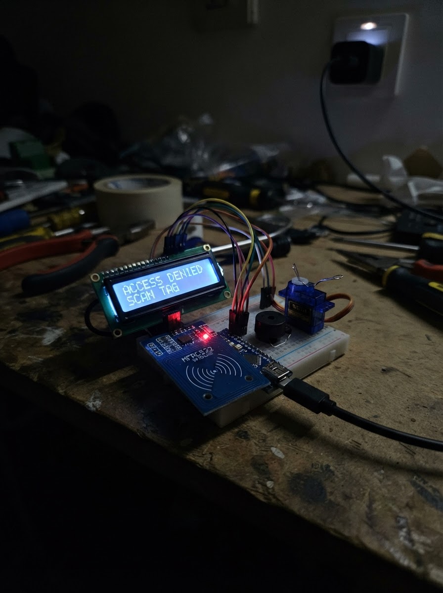
This RFID access control system uses an Arduino Uno to read RFID cards and control a servo-driven lock mechanism. When an authorized card is scanned, the system unlocks the door for a set duration, displays status messages on an LCD screen, and provides audio feedback via a buzzer. The guide includes a complete wiring diagram, parts list, and step-by-step assembly instructions to get the system operational.
Builders will learn how to integrate SPI communication with the MFRC522 RFID reader, I2C control of the LCD display, and servo actuation for the lock mechanism. The provided Arduino firmware handles card detection, authorization logic, and timed lock/unlock sequences, making this an excellent foundation for understanding access control systems and multi-component Arduino projects.
Wiring diagram

Gather all the parts
Assemble it in 5 steps
1. Arrange the dark circuit layout
Place the Arduino Uno centrally on a dark gray breadboard or mounting panel. Position the RC522 reader to its left, the LCD above it, the SG90 at the right, and the piezo buzzer at the lower right. Keep the RFID antenna clear of metal and large wire bundles.
- Use short, neatly routed jumper wires so the diagram-like layout stays easy to trace.
- Keep the RC522 antenna face exposed for reliable card scans.
- Do not place the RC522 directly on a metal plate or against the Uno USB connector.
2. Wire the RC522 RFID reader
Connect RC522 VCC to the Uno 3.3 V rail and GND to common ground. Connect SCK to D13, MOSI to D11, MISO to D12, SDA/SS to D10, and RST to D9. For a physical 5 V Uno, insert 5 V-to-3.3 V resistor dividers or a proper high-speed level shifter on the Uno outputs D13, D11, D10, and D9 before they reach the RC522 inputs.
- The RC522 pin labelled SDA is SPI chip select, not I2C SDA.
- Use 1 kΩ from each Uno output to the RC522 input node and 2 kΩ from that node to GND for each divider.
- Never connect RC522 VCC to 5 V.
- Do not omit the level reduction on D13, D11, D10, and D9; RC522 logic is 3.3 V.
3. Wire the I2C LCD
Connect LCD VCC to 5 V and GND to common ground. Connect LCD SDA to Uno A4 and LCD SCL to Uno A5.
- Most 16x2 I2C backpacks use address 0x27; the supplied firmware uses that address.
- Adjust the small contrast trimmer on the LCD backpack if characters are not visible.
- Keep A4 and A5 exclusively for the I2C LCD bus in this project.
4. Wire the buzzer and servo
Connect buzzer SIGNAL to D3 and buzzer GND to common ground. Connect the SG90 signal wire (orange/yellow) to D6, its red wire to regulated 5 V, and its brown/black wire to common ground.
- Set the servo horn mechanically after the firmware first moves it to the locked position.
- Add a 470–1000 µF electrolytic capacitor across the 5 V and GND rails close to the servo if you see resets or LCD flicker.
- Do not rely on the Uno 5 V pin alone to power a mechanically loaded servo.
- The servo supply ground and Uno ground must be connected together.
5. Connect regulated power and inspect
Use the regulated 5 V, 2 A minimum USB power adapter to feed the project 5 V and GND rails. Confirm that the Uno receives power through its normal USB input or a safe regulated 5 V distribution, and verify every module shares the same ground before powering on.
- Route red wires as 5 V, black wires as ground, and use distinct colors for SPI, I2C, and servo signal wires to create a realistic easy-to-read diagram.
- After powering, scan any 13.56 MHz card or fob: its UID appears on the LCD, the buzzer chirps, and the servo unlocks briefly.
- Do not connect two independent 5 V sources to the Uno 5 V rail at the same time.
- Double-check RC522 power polarity before turning on the supply.
Review all connections
1. Connections between "power_adapter" and "Arduino"
2. Connections between "rfid_reader" and "Arduino"
3. Connections between "lcd_display" and "Arduino"
4. Connections between "piezo_buzzer" and "Arduino"
5. Connections between "servo_motor" and "Arduino"
Deploy the firmware
#include <Arduino.h>
#include <SPI.h>
#include <MFRC522.h>
#include <Wire.h>
#include <LiquidCrystal_I2C.h>
#include <Servo.h>


// Forward declarations
void showStatus(const String &line1, const String &line2);
String cardUid();
void lockDoor();
void unlockDoor(const String &uid);

const byte RFID_SS_PIN = 10;
const byte RFID_RST_PIN = 9;
const byte BUZZER_PIN = 3;
const byte SERVO_PIN = 6;
const byte SERVO_LOCKED_ANGLE = 10;
const byte SERVO_UNLOCKED_ANGLE = 95;
const unsigned long UNLOCK_TIME_MS = 3000UL;

MFRC522 rfid(RFID_SS_PIN, RFID_RST_PIN);
LiquidCrystal_I2C lcd(0x27, 16, 2);
Servo lockServo;
bool doorUnlocked = false;
unsigned long unlockStartedAt = 0;
String shownLine1;
String shownLine2;

void showStatus(const String &line1, const String &line2) {
  if (line1 == shownLine1 && line2 == shownLine2) return;
  lcd.setCursor(0, 0); lcd.print("                ");
  lcd.setCursor(0, 0); lcd.print(line1.substring(0, 16));
  lcd.setCursor(0, 1); lcd.print("                ");
  lcd.setCursor(0, 1); lcd.print(line2.substring(0, 16));
  shownLine1 = line1;
  shownLine2 = line2;
}

String cardUid() {
  String uid;
  for (byte i = 0; i < rfid.uid.size; ++i) {
    if (rfid.uid.uidByte[i] < 0x10) uid += '0';
    uid += String(rfid.uid.uidByte[i], HEX);
    if (i + 1 < rfid.uid.size) uid += ':';
  }
  uid.toUpperCase();
  return uid;
}

void lockDoor() {
  lockServo.write(SERVO_LOCKED_ANGLE);
  doorUnlocked = false;
  showStatus("Scan RFID card", "Door locked");
}

void unlockDoor(const String &uid) {
  lockServo.write(SERVO_UNLOCKED_ANGLE);
  doorUnlocked = true;
  unlockStartedAt = millis();
  showStatus("Access granted", uid);
  tone(BUZZER_PIN, 1600, 110);
  delay(140);
  tone(BUZZER_PIN, 2200, 140);
}

void setup() {
  pinMode(BUZZER_PIN, OUTPUT);
  Wire.begin();
  lcd.init();
  lcd.backlight();
  lockServo.attach(SERVO_PIN);
  SPI.begin();
  rfid.PCD_Init();
  delay(50);
  lockDoor();
}

void loop() {
  if (doorUnlocked && millis() - unlockStartedAt >= UNLOCK_TIME_MS) lockDoor();
  if (!rfid.PICC_IsNewCardPresent() || !rfid.PICC_ReadCardSerial()) return;
  String uid = cardUid();
  unlockDoor(cardUid());
  rfid.PICC_HaltA();
  rfid.PCD_StopCrypto1();
}
Remix this project
Make it yours in one click
Open a full copy of this project in your own Schematik workspace — diagram, code, parts, and assembly steps included. Swap the sensor, add features, or redesign the whole thing with AI. The author's original stays untouched.