Community project
RFID Smart Door Access
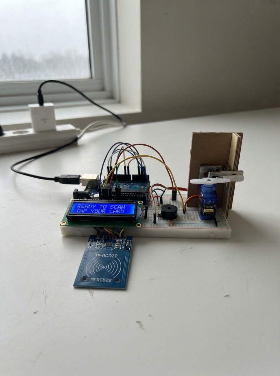
This project builds an RFID-based door access system using an ESP32 microcontroller to read NFC/RFID cards and control a servo-driven latch. The system authenticates users by comparing scanned card UIDs against an enrolled credential, then unlocks the door for a configurable duration while providing visual and audio feedback through an LCD display and buzzer.
The guide includes a complete wiring diagram, parts list, and step-by-step assembly instructions for integrating the MFRC522 RFID reader, I2C LCD display, servo motor, and buzzer. The provided firmware handles card enrollment, access control logic, and automatic re-locking, ready to upload directly to the ESP32.
Wiring diagram

Gather all the parts
Assemble it in 5 steps
1. Prepare the low-voltage power
Use a regulated 5 V wall adapter rated for at least 2 A. Connect its +5 V output to the ESP32 VIN/5V pin, the SG90 red wire, and the LCD VCC pin. Connect its ground to ESP32 GND, the servo brown/black wire, LCD GND, RFID GND, and buzzer GND.
- Keep servo power wires short and use a 470–1000 µF electrolytic capacitor across 5 V and GND close to the servo: capacitor + to 5 V and − to GND.
- Every module must share the same ground.
- Never connect the servo to the ESP32 3.3 V pin.
- Do not use an unregulated supply or expose any mains wiring.
2. Wire the RC522 RFID reader at 3.3 V
Connect RC522 VCC to ESP32 3V3, GND to GND, SCK to GPIO18, MOSI to GPIO23, MISO to GPIO19, SDA/SS to GPIO4, and RST to GPIO26.
- The RC522 SDA pin is its SPI select pin; it is not the I2C SDA line.
- Keep the RC522 away from large metal parts of the door where possible.
- RC522 VCC is 3.3 V only. Applying 5 V can damage it.
3. Wire the I2C LCD safely
Connect LCD VCC to ESP32 3V3, GND to GND, SDA to GPIO21, and SCL to GPIO22. This design assumes a 3.3 V-compatible I2C LCD backpack and uses address 0x27.
- If the display stays blank, carefully adjust its small contrast potentiometer.
- Some LCD backpacks use address 0x3F; the firmware currently uses 0x27.
- Do not power a standard pull-up-equipped I2C LCD backpack from 5 V directly on ESP32 SDA/SCL. Its pull-ups may drive the ESP32’s 3.3 V pins to 5 V. Use 3.3 V as wired, or add a proper bidirectional I2C level shifter.
4. Connect the latch servo and buzzer
Connect the SG90 orange/yellow signal wire to GPIO25, red to the 5 V supply, and brown/black to common ground. Connect the active buzzer module SIGNAL to GPIO33 and its GND to common ground.
- Before attaching the servo horn to the latch, power the project so the firmware moves it to the locked position, then fit the horn mechanically.
- Adjust LOCK_ANGLE and UNLOCK_ANGLE in firmware later if your latch moves the wrong amount.
- An SG90 is suitable for a model latch/light mechanism, not as the only security mechanism for a real exterior door.
- Use a buzzer module whose input recognizes 3.3 V logic; a bare high-current buzzer requires a transistor driver.
5. Mount and test mechanically
Mount the RC522 where cards can reach it, then connect the servo horn to a light latch linkage. Keep the door able to open manually in an emergency. On first boot, scan the card you want to authorize; it is saved in ESP32 memory. Scan that card again to unlock for five seconds.
- Test repeatedly with the door open before fitting it to a door.
- The LCD shows enrollment, access-granted, denied, and locked status.
- Do not rely on RFID UID matching alone for high-security access: many low-cost RFID tags can be cloned. Use a certified lock, mechanical override, and stronger authenticated credentials for real security.
Review all connections
1. Connections between "power_adapter" and "ESP32"
2. Connections between "rfid_reader" and "ESP32"
3. Connections between "lcd" and "ESP32"
4. Connections between "door_servo" and "ESP32"
5. Connections between "buzzer" and "ESP32"
Deploy the firmware
#include <Arduino.h>
#include <SPI.h>
#include <Wire.h>
#include <MFRC522.h>
#include <LiquidCrystal_I2C.h>
#include <ESP32Servo.h>
#include <Preferences.h>


// Forward declarations
String uidToString(const MFRC522::Uid &uid);
void showMessage(const String &line1, const String &line2);
void beep(unsigned int durationMs);
void lockDoor(bool announce);
void unlockDoor();
void denyAccess();

constexpr uint8_t RFID_SS_PIN = 4;
constexpr uint8_t RFID_RST_PIN = 26;
constexpr uint8_t RFID_SCK_PIN = 18;
constexpr uint8_t RFID_MISO_PIN = 19;
constexpr uint8_t RFID_MOSI_PIN = 23;
constexpr uint8_t LCD_SDA_PIN = 21;
constexpr uint8_t LCD_SCL_PIN = 22;
constexpr uint8_t SERVO_PIN = 25;
constexpr uint8_t BUZZER_PIN = 33;
constexpr int LOCK_ANGLE = 10;
constexpr int UNLOCK_ANGLE = 90;
constexpr unsigned long UNLOCK_TIME_MS = 5000;
constexpr unsigned long CARD_COOLDOWN_MS = 1200;

MFRC522 rfid(RFID_SS_PIN, RFID_RST_PIN);
LiquidCrystal_I2C lcd(0x27, 16, 2);
Servo latchServo;
Preferences preferences;
String enrolledUid;
String lastMessage;
unsigned long unlockStartedAt = 0;
unsigned long lastCardAt = 0;
bool doorUnlocked = false;

String uidToString(const MFRC522::Uid &uid) {
  String value;
  for (byte i = 0; i < uid.size; ++i) {
    if (uid.uidByte[i] < 0x10) value += "0";
    value += String(uid.uidByte[i], HEX);
  }
  value.toUpperCase();
  return value;
}

void showMessage(const String &line1, const String &line2) {
  String message = line1 + "\n" + line2;
  if (message == lastMessage) return;
  lastMessage = message;
  lcd.clear();
  lcd.setCursor(0, 0);
  lcd.print(line1.substring(0, 16));
  lcd.setCursor(0, 1);
  lcd.print(line2.substring(0, 16));
}

void beep(unsigned int durationMs) {
  digitalWrite(BUZZER_PIN, HIGH);
  delay(durationMs);
  digitalWrite(BUZZER_PIN, LOW);
}

void lockDoor(bool announce = true) {
  latchServo.write(LOCK_ANGLE);
  doorUnlocked = false;
  if (announce) showMessage("Door locked", "Present card");
}

void unlockDoor() {
  latchServo.write(UNLOCK_ANGLE);
  doorUnlocked = true;
  unlockStartedAt = millis();
  showMessage("Access granted", "Door unlocked");
  beep(90);
  delay(70);
  beep(90);
}

void denyAccess() {
  showMessage("Access denied", "Unknown card");
  beep(600);
}

void setup() {
  Serial.begin(115200);
  pinMode(BUZZER_PIN, OUTPUT);
  digitalWrite(BUZZER_PIN, LOW);
  Wire.begin(LCD_SDA_PIN, LCD_SCL_PIN);
  lcd.init();
  lcd.backlight();
  showMessage("Smart Door", "Starting...");
  latchServo.setPeriodHertz(50);
  latchServo.attach(SERVO_PIN, 500, 2400);
  lockDoor(false);
  SPI.begin(RFID_SCK_PIN, RFID_MISO_PIN, RFID_MOSI_PIN, RFID_SS_PIN);
  rfid.PCD_Init();
  preferences.begin("door-access", false);
  enrolledUid = preferences.getString("adminUid", "");
  if (enrolledUid.length() == 0) {
    showMessage("Enroll first card", "Scan RFID card");
    Serial.println("Enrollment mode: scan the first card to authorize it.");
  } else {
    showMessage("Door locked", "Present card");
  }
}

void loop() {
  if (doorUnlocked && millis() - unlockStartedAt >= UNLOCK_TIME_MS) lockDoor();
  if (!rfid.PICC_IsNewCardPresent() || !rfid.PICC_ReadCardSerial()) return;
  if (millis() - lastCardAt < CARD_COOLDOWN_MS) {
    rfid.PICC_HaltA();
    rfid.PCD_StopCrypto1();
    return;
  }
  lastCardAt = millis();
  const String scannedUid = uidToString(rfid.uid);
  Serial.println("Scanned UID: " + scannedUid);
  if (enrolledUid.length() == 0) {
    enrolledUid = scannedUid;
    preferences.putString("adminUid", enrolledUid);
    showMessage("Card enrolled", "Scan to unlock");
    beep(120);
    delay(80);
    beep(120);
  } else if (scannedUid == enrolledUid) {
    unlockDoor();
  } else {
    denyAccess();
  }
  rfid.PICC_HaltA();
  rfid.PCD_StopCrypto1();
}
Remix this project
Make it yours in one click
Open a full copy of this project in your own Schematik workspace — diagram, code, parts, and assembly steps included. Swap the sensor, add features, or redesign the whole thing with AI. The author's original stays untouched.
Related projects

Create A Complete Electrical Schematic Esp32 Sma
ESP32 · September 17, 2026Ayansh Agrawal
ESP32 Kare Ekran Projeleri
ESP32 · September 16, 2026Seref Ai
Component Qty --------------------------- ------
ESP32 · September 16, 2026Yathartha Chakrawal