Community project
RFID Smart Door Access
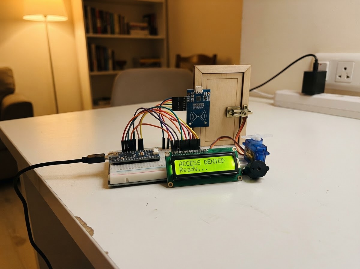
This project builds a card-based door access system using an ESP32 microcontroller and RFID reader. When an authorized card is presented, the system unlocks an electronic latch via servo motor, displays status on an LCD screen, and provides audio feedback through a buzzer. The guide includes a complete wiring diagram, parts list, and step-by-step assembly instructions for integrating the RFID module, I2C display, servo actuator, and buzzer into a functional access control system.
The firmware stores an enrolled card UID in non-volatile memory and compares incoming scans against it, triggering unlock sequences only for authorized cards. Readers will learn how to wire low-voltage components safely, configure SPI and I2C communication on the ESP32, control a servo latch mechanism, and implement basic access logic with visual and audio feedback.
Wiring diagram

Gather all the parts
Assemble it in 5 steps
1. Prepare the low-voltage power
Use a regulated 5 V wall adapter rated for at least 2 A. Connect its +5 V output to the ESP32 VIN/5V pin, the SG90 red wire, and the LCD VCC pin. Connect its ground to ESP32 GND, the servo brown/black wire, LCD GND, RFID GND, and buzzer GND.
- Keep servo power wires short and use a 470–1000 µF electrolytic capacitor across 5 V and GND close to the servo: capacitor + to 5 V and − to GND.
- Every module must share the same ground.
- Never connect the servo to the ESP32 3.3 V pin.
- Do not use an unregulated supply or expose any mains wiring.
2. Wire the RC522 RFID reader at 3.3 V
Connect RC522 VCC to ESP32 3V3, GND to GND, SCK to GPIO18, MOSI to GPIO23, MISO to GPIO19, SDA/SS to GPIO4, and RST to GPIO26.
- The RC522 SDA pin is its SPI select pin; it is not the I2C SDA line.
- Keep the RC522 away from large metal parts of the door where possible.
- RC522 VCC is 3.3 V only. Applying 5 V can damage it.
3. Wire the I2C LCD safely
Connect LCD VCC to ESP32 3V3, GND to GND, SDA to GPIO21, and SCL to GPIO22. This design assumes a 3.3 V-compatible I2C LCD backpack and uses address 0x27.
- If the display stays blank, carefully adjust its small contrast potentiometer.
- Some LCD backpacks use address 0x3F; the firmware currently uses 0x27.
- Do not power a standard pull-up-equipped I2C LCD backpack from 5 V directly on ESP32 SDA/SCL. Its pull-ups may drive the ESP32’s 3.3 V pins to 5 V. Use 3.3 V as wired, or add a proper bidirectional I2C level shifter.
4. Connect the latch servo and buzzer
Connect the SG90 orange/yellow signal wire to GPIO25, red to the 5 V supply, and brown/black to common ground. Connect the active buzzer module SIGNAL to GPIO33 and its GND to common ground.
- Before attaching the servo horn to the latch, power the project so the firmware moves it to the locked position, then fit the horn mechanically.
- Adjust LOCK_ANGLE and UNLOCK_ANGLE in firmware later if your latch moves the wrong amount.
- An SG90 is suitable for a model latch/light mechanism, not as the only security mechanism for a real exterior door.
- Use a buzzer module whose input recognizes 3.3 V logic; a bare high-current buzzer requires a transistor driver.
5. Mount and test mechanically
Mount the RC522 where cards can reach it, then connect the servo horn to a light latch linkage. Keep the door able to open manually in an emergency. On first boot, scan the card you want to authorize; it is saved in ESP32 memory. Scan that card again to unlock for five seconds.
- Test repeatedly with the door open before fitting it to a door.
- The LCD shows enrollment, access-granted, denied, and locked status.
- Do not rely on RFID UID matching alone for high-security access: many low-cost RFID tags can be cloned. Use a certified lock, mechanical override, and stronger authenticated credentials for real security.
Review all connections
1. Connections between "power_adapter" and "ESP32"
2. Connections between "rfid_reader" and "ESP32"
3. Connections between "lcd" and "ESP32"
4. Connections between "door_servo" and "ESP32"
5. Connections between "buzzer" and "ESP32"
Deploy the firmware
#include <Arduino.h>
#include <SPI.h>
#include <Wire.h>
#include <MFRC522.h>
#include <LiquidCrystal_I2C.h>
#include <ESP32Servo.h>
#include <Preferences.h>


// Forward declarations
String uidToString(const MFRC522::Uid &uid);
void showMessage(const String &line1, const String &line2);
void beep(unsigned int durationMs);
void lockDoor(bool announce);
void unlockDoor();
void denyAccess();

constexpr uint8_t RFID_SS_PIN = 4;
constexpr uint8_t RFID_RST_PIN = 26;
constexpr uint8_t RFID_SCK_PIN = 18;
constexpr uint8_t RFID_MISO_PIN = 19;
constexpr uint8_t RFID_MOSI_PIN = 23;
constexpr uint8_t LCD_SDA_PIN = 21;
constexpr uint8_t LCD_SCL_PIN = 22;
constexpr uint8_t SERVO_PIN = 25;
constexpr uint8_t BUZZER_PIN = 33;
constexpr int LOCK_ANGLE = 10;
constexpr int UNLOCK_ANGLE = 90;
constexpr unsigned long UNLOCK_TIME_MS = 5000;
constexpr unsigned long CARD_COOLDOWN_MS = 1200;

MFRC522 rfid(RFID_SS_PIN, RFID_RST_PIN);
LiquidCrystal_I2C lcd(0x27, 16, 2);
Servo latchServo;
Preferences preferences;
String enrolledUid;
String lastMessage;
unsigned long unlockStartedAt = 0;
unsigned long lastCardAt = 0;
bool doorUnlocked = false;

String uidToString(const MFRC522::Uid &uid) {
  String value;
  for (byte i = 0; i < uid.size; ++i) {
    if (uid.uidByte[i] < 0x10) value += "0";
    value += String(uid.uidByte[i], HEX);
  }
  value.toUpperCase();
  return value;
}

void showMessage(const String &line1, const String &line2) {
  String message = line1 + "\n" + line2;
  if (message == lastMessage) return;
  lastMessage = message;
  lcd.clear();
  lcd.setCursor(0, 0);
  lcd.print(line1.substring(0, 16));
  lcd.setCursor(0, 1);
  lcd.print(line2.substring(0, 16));
}

void beep(unsigned int durationMs) {
  digitalWrite(BUZZER_PIN, HIGH);
  delay(durationMs);
  digitalWrite(BUZZER_PIN, LOW);
}

void lockDoor(bool announce = true) {
  latchServo.write(LOCK_ANGLE);
  doorUnlocked = false;
  if (announce) showMessage("Door locked", "Present card");
}

void unlockDoor() {
  latchServo.write(UNLOCK_ANGLE);
  doorUnlocked = true;
  unlockStartedAt = millis();
  showMessage("Access granted", "Door unlocked");
  beep(90);
  delay(70);
  beep(90);
}

void denyAccess() {
  showMessage("Access denied", "Unknown card");
  beep(600);
}

void setup() {
  Serial.begin(115200);
  pinMode(BUZZER_PIN, OUTPUT);
  digitalWrite(BUZZER_PIN, LOW);
  Wire.begin(LCD_SDA_PIN, LCD_SCL_PIN);
  lcd.init();
  lcd.backlight();
  showMessage("Smart Door", "Starting...");
  latchServo.setPeriodHertz(50);
  latchServo.attach(SERVO_PIN, 500, 2400);
  lockDoor(false);
  SPI.begin(RFID_SCK_PIN, RFID_MISO_PIN, RFID_MOSI_PIN, RFID_SS_PIN);
  rfid.PCD_Init();
  preferences.begin("door-access", false);
  enrolledUid = preferences.getString("adminUid", "");
  if (enrolledUid.length() == 0) {
    showMessage("Enroll first card", "Scan RFID card");
    Serial.println("Enrollment mode: scan the first card to authorize it.");
  } else {
    showMessage("Door locked", "Present card");
  }
}

void loop() {
  if (doorUnlocked && millis() - unlockStartedAt >= UNLOCK_TIME_MS) lockDoor();
  if (!rfid.PICC_IsNewCardPresent() || !rfid.PICC_ReadCardSerial()) return;
  if (millis() - lastCardAt < CARD_COOLDOWN_MS) {
    rfid.PICC_HaltA();
    rfid.PCD_StopCrypto1();
    return;
  }
  lastCardAt = millis();
  const String scannedUid = uidToString(rfid.uid);
  Serial.println("Scanned UID: " + scannedUid);
  if (enrolledUid.length() == 0) {
    enrolledUid = scannedUid;
    preferences.putString("adminUid", enrolledUid);
    showMessage("Card enrolled", "Scan to unlock");
    beep(120);
    delay(80);
    beep(120);
  } else if (scannedUid == enrolledUid) {
    unlockDoor();
  } else {
    denyAccess();
  }
  rfid.PICC_HaltA();
  rfid.PCD_StopCrypto1();
}
Remix this project
Make it yours in one click
Open a full copy of this project in your own Schematik workspace — diagram, code, parts, and assembly steps included. Swap the sensor, add features, or redesign the whole thing with AI. The author's original stays untouched.