Community project
ROVIE: ESP32 Obstacle Avoiding Rover
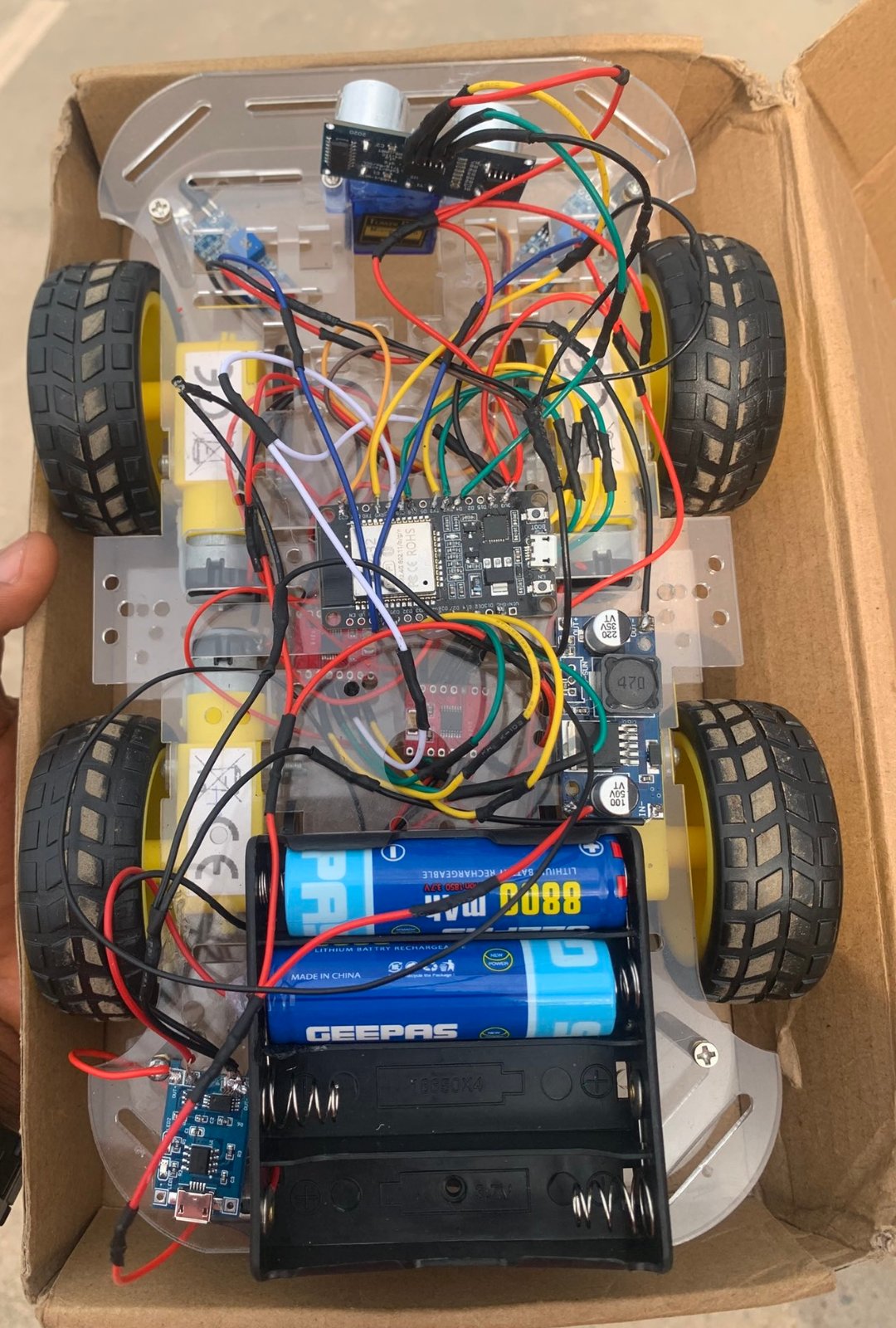
ROVIE is a four-wheel drive obstacle-avoiding rover that combines line-following and distance-sensing capabilities. Built around an ESP32 microcontroller, it uses an L298N motor driver to control four DC motors, dual TCRT5000 IR sensors to detect black lines, and an HC-SR04 ultrasonic sensor to measure distances and avoid collisions. This guide provides a complete wiring diagram, parts list, and step-by-step assembly instructions to get ROVIE navigating autonomously.
The included Arduino firmware implements real-time motor control with PWM speed adjustment, line-tracking logic that keeps ROVIE centered on a black line, and obstacle detection that triggers avoidance maneuvers when objects approach within 20 cm. Builders will learn how to wire a multi-motor system, configure ESP32 GPIO pins for sensor input and PWM output, and program autonomous navigation behaviors.
Wiring diagram

Gather all the parts
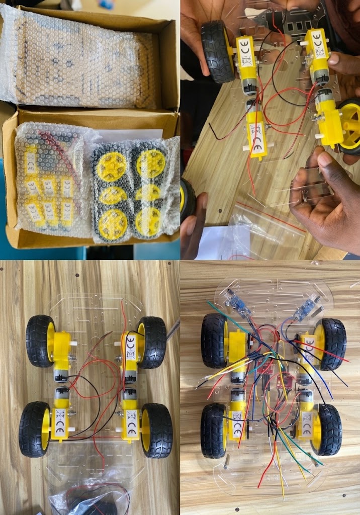
Assemble it in 5 steps
1. Mount the four motors and driver
Fix the four TT gear motors to the chassis (two on the left side, two on the right). Mount the L298N board in the middle. The two left motors will act as one pair, and the two right motors as the other pair.
2. Wire the motors to the driver
Connect both left motors together and run them to the L298N OUT1/OUT2 screw terminals. Connect both right motors together and run them to OUT3/OUT4. If a side spins backward later, just swap that side's two wires.
- Twist each motor pair's matching wires together before screwing them into one terminal.
3. Set up battery power
Connect the battery pack's positive wire to the L298N VS terminal and also to the buck converter input (VIN+). Connect the battery negative to the L298N GND and buck converter input ground (VIN-). The buck converter's 5V output feeds the L298N 5V logic pin, both IR sensors, and the HC-SR04.
- Set the buck converter to 5V with a multimeter BEFORE connecting the ESP32 and sensors — too high a voltage can destroy them.
4. Power the ESP32 and share ground
Feed the buck converter's 5V into the ESP32 VIN pin, and connect the buck 5V to the sensors' VCC pins. Tie ALL grounds together — battery, buck, L298N, ESP32 GND, IR sensors, and HC-SR04 must share one common ground, or the signals won't read correctly.
- A missing common ground is the most common reason motors twitch and sensors read garbage.
5. Wire the control signals
L298N IN1→GPIO13, IN2→GPIO14, IN3→GPIO26, IN4→GPIO27, ENA→GPIO25, ENB→GPIO33 (remove the ENA/ENB jumpers so speed control works). Left IR DO→GPIO32, right IR DO→GPIO4. HC-SR04 TRIG→GPIO16, ECHO→GPIO17.
- Mount the two IR sensors underneath the front, close to the floor, one on each side of the line.
- Mount the ultrasonic sensor facing forward at the front.
Review all connections
1. Connections between "battery" and "ESP32"
2. Connections between "buck5v" and "ESP32"
3. Connections between "l298n" and "ESP32"
4. Connections between "motor_fl" and "ESP32"
5. Connections between "motor_fr" and "ESP32"
6. Connections between "ir_left" and "ESP32"
7. Connections between "ir_right" and "ESP32"
8. Connections between "sonar" and "ESP32"
9. Connections between "motor_rl" and "ESP32"
10. Connections between "motor_rr" and "ESP32"
Deploy the firmware
#include <Arduino.h>
// 4WD line-following + obstacle-avoiding robot
// ESP32 DevKit v1 + L298N + 4x TT motors + 2x TCRT5000 IR + HC-SR04
//
// Left side (front-left + rear-left) share L298N bridge A (OUT1/OUT2, IN1/IN2, ENA).
// Right side (front-right + rear-right) share bridge B (OUT3/OUT4, IN3/IN4, ENB).

// --- Motor driver pins ---

// Forward declarations
void leftSpeed(int s);
void rightSpeed(int s);
void leftForward();
void leftReverse();
void rightForward();
void rightReverse();
void driveForward();
void turnLeft();
void turnRight();
void stopMotors();
long readDistanceCm();

const int IN1 = 13;  // Bridge A dir
const int IN2 = 14;  // Bridge A dir
const int IN3 = 26;  // Bridge B dir
const int IN4 = 27;  // Bridge B dir
const int ENA = 25;  // Bridge A speed (PWM) - LEFT
const int ENB = 33;  // Bridge B speed (PWM) - RIGHT

// --- Sensors ---
const int IR_LEFT  = 32; // TCRT5000 DO: LOW over black line
const int IR_RIGHT = 4;
const int TRIG = 16;
const int ECHO = 17;     // input-capable GPIO

// --- LEDC PWM setup (ESP32) ---
const int CH_A = 0;
const int CH_B = 1;
const int PWM_FREQ = 1000;
const int PWM_RES  = 8;   // 0..255

const int SPEED_FWD  = 200;
const int SPEED_TURN = 180;

const int OBSTACLE_CM = 20; // stop/avoid closer than this

void leftSpeed(int s)  { ledcWrite(CH_A, s); }
void rightSpeed(int s) { ledcWrite(CH_B, s); }

void leftForward()  { digitalWrite(IN1, HIGH); digitalWrite(IN2, LOW); }
void leftReverse()  { digitalWrite(IN1, LOW);  digitalWrite(IN2, HIGH); }
void rightForward() { digitalWrite(IN3, HIGH); digitalWrite(IN4, LOW); }
void rightReverse() { digitalWrite(IN3, LOW);  digitalWrite(IN4, HIGH); }

void driveForward() { leftForward(); rightForward(); leftSpeed(SPEED_FWD); rightSpeed(SPEED_FWD); }
void turnLeft()     { leftReverse(); rightForward(); leftSpeed(SPEED_TURN); rightSpeed(SPEED_TURN); }
void turnRight()    { leftForward(); rightReverse(); leftSpeed(SPEED_TURN); rightSpeed(SPEED_TURN); }
void stopMotors()   { leftSpeed(0); rightSpeed(0); }

long readDistanceCm() {
  digitalWrite(TRIG, LOW);
  delayMicroseconds(2);
  digitalWrite(TRIG, HIGH);
  delayMicroseconds(10);
  digitalWrite(TRIG, LOW);
  // 25ms timeout ~ 4.3m max
  unsigned long dur = pulseIn(ECHO, HIGH, 25000UL);
  if (dur == 0) return 999; // no echo = treat as clear
  return (long)(dur / 58);
}

void setup() {
  Serial.begin(115200);
  pinMode(IN1, OUTPUT); pinMode(IN2, OUTPUT);
  pinMode(IN3, OUTPUT); pinMode(IN4, OUTPUT);
  pinMode(IR_LEFT, INPUT); pinMode(IR_RIGHT, INPUT);
  pinMode(TRIG, OUTPUT); pinMode(ECHO, INPUT);

  ledcSetup(CH_A, PWM_FREQ, PWM_RES);
  ledcSetup(CH_B, PWM_FREQ, PWM_RES);
  ledcAttachPin(ENA, CH_A);
  ledcAttachPin(ENB, CH_B);

  stopMotors();
}

void loop() {
  long dist = readDistanceCm();

  // Obstacle avoidance takes priority
  if (dist <= OBSTACLE_CM) {
    stopMotors();
    delay(120);
    // back up briefly then pivot to look for a clear path
    leftReverse(); rightReverse();
    leftSpeed(SPEED_TURN); rightSpeed(SPEED_TURN);
    delay(300);
    turnRight();
    delay(400);
    stopMotors();
    return;
  }

  // Line following: DO LOW = over black line
  bool leftOnLine  = (digitalRead(IR_LEFT)  == LOW);
  bool rightOnLine = (digitalRead(IR_RIGHT) == LOW);

  if (!leftOnLine && !rightOnLine) {
    driveForward();               // both on white -> go straight
  } else if (leftOnLine && !rightOnLine) {
    turnLeft();                   // line drifted left -> steer left
  } else if (!leftOnLine && rightOnLine) {
    turnRight();                  // line drifted right -> steer right
  } else {
    // both on black (junction/stop mark) -> creep forward slowly
    driveForward();
    leftSpeed(SPEED_TURN); rightSpeed(SPEED_TURN);
  }
}
Download project files
Remix this project
Make it yours in one click
Open a full copy of this project in your own Schematik workspace — diagram, code, parts, and assembly steps included. Swap the sensor, add features, or redesign the whole thing with AI. The author's original stays untouched.