Community project
Self-Balancing Line-Following Robot
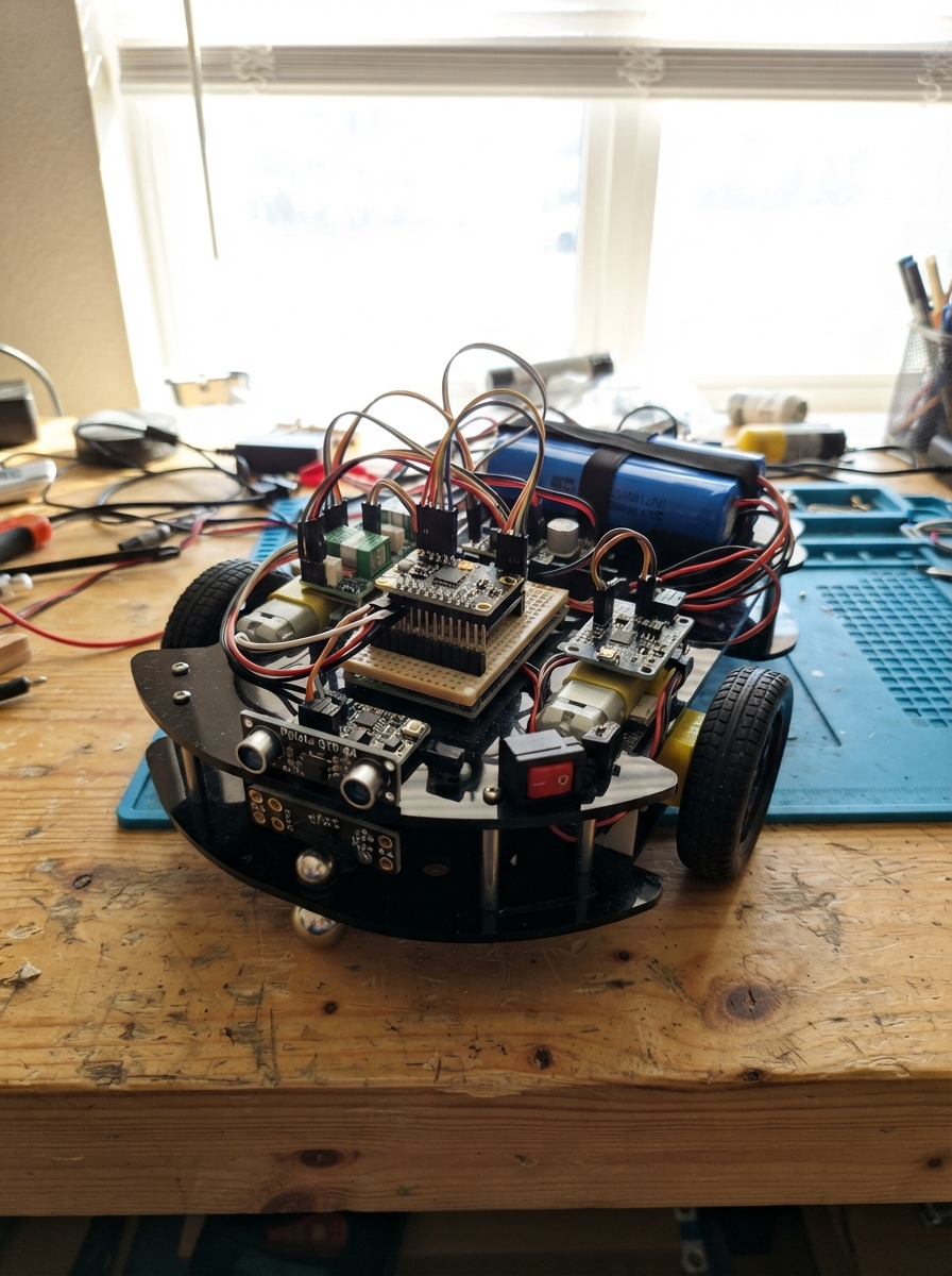
This guide builds a self-balancing robot that follows a line using an ESP32 microcontroller, dual N20 motors with encoders, and an MPU-6050 IMU for real-time balance control. The robot uses a Pololu QTR-8A reflectance sensor array to detect and track a dark line while maintaining upright stability through cascaded PID control loops.
The guide provides a complete wiring diagram, detailed parts list with power distribution design, and firmware with tunable balance and steering gains. Assembly steps cover battery pack protection, regulated 5V and 3.3V supplies, motor driver integration, encoder wiring, and safe initial testing procedures before autonomous operation.
Wiring diagram

Gather all the parts
Assemble it in 6 steps
1. Build the protected battery pack
Make a 3S1P pack using three matched Samsung INR18650-25R cells in series, with nickel strips or a proper holder. Connect the pack positive lead to bms_3s B+ and the pack negative lead to bms_3s B-. Connect the BMS sense wires to each cell junction exactly as marked on its board.
- Place the battery low and centered between the wheels; this helps the robot balance.
- Use pre-welded cells or a proper spot welder, not a soldering iron directly on bare cells.
- A wrong BMS sense-wire order can instantly damage the BMS or battery pack. A 3S pack is 12.6 V when full, so never connect it directly to ESP32 or 6 V motors.
2. Make the 5 V and 3.3 V supplies
Connect bms_3s P+ to power_switch T1, then power_switch T2 to buck_5v VIN+. Connect bms_3s P- to buck_5v VIN- (ground). Before connecting anything else, adjust buck_5v VOUT+ to exactly 5.0 V with a multimeter. Connect buck_5v VOUT+ to ldo_3v3 VIN, and buck_5v VOUT- to ldo_3v3 GND. The ldo_3v3 VOUT pin is the 3.3 V rail.
- Keep all ground wires joined: battery negative, both regulator grounds, ESP32 ground, driver ground, and sensor grounds.
- The 5 V rail powers the ESP32 VIN pin and motor driver VM pin; the 3.3 V rail powers sensor and driver logic.
- Measure the LM2596 output before attaching the ESP32. More than 5 V can damage the board. The AMS1117 gets warm; do not use it for motor power.
3. Install the motors and driver
Mount left_motor and right_motor firmly on the chassis with their shafts level. Connect motor_driver A01 and A02 to the two left_motor motor terminals, and B01 and B02 to the two right_motor motor terminals. Connect motor_driver VM to the 5 V LM2596 output (motor power), VCC to AMS1117 3.3 V (logic power), and GND to shared ground (ground).
- If a wheel turns the wrong way during testing, swap that motor’s two motor wires.
- Use short, thicker wires for the motor power path.
- Do not let motor wires touch each other; a short can heat wires and trip the battery protection board.
4. Connect the ESP32 control wires
Connect motor_driver AIN1 to GPIO4 (left direction), AIN2 to GPIO13 (left direction), PWMA to GPIO14 (left speed), BIN1 to GPIO16 (right direction), BIN2 to GPIO17 (right direction), PWMB to GPIO18 (right speed), and STBY to GPIO19 (driver enable). Connect the ESP32 VIN pin to the regulated 5 V rail (power) and ESP32 GND to shared ground (ground). Connect each motor encoder VCC to 3.3 V and encoder GND to ground; left ENC_A to GPIO23 (signal), left ENC_B to GPIO25 (signal), right ENC_A to GPIO26 (signal), and right ENC_B to GPIO27 (signal).
- Keep encoder wires away from motor leads where possible, because motor electrical noise can confuse the wheel counts.
- Never connect a 5 V encoder signal to the ESP32. This design powers encoders from 3.3 V so their signals are safe.
5. Wire the balance and line sensors
Connect imu VIN to 3.3 V (power), imu GND to ground (ground), imu SDA to GPIO21 (data), and imu SCL to GPIO22 (data). Connect line_array VCC to 3.3 V (power) and GND to ground (ground). Connect OUT1 through OUT4 to line_adc_left AIN0 through AIN3; connect OUT5 through OUT8 to line_adc_right AIN0 through AIN3. Power both ADC boards from 3.3 V and ground, and connect both SDA pins to GPIO21 (data) and both SCL pins to GPIO22 (data). Connect line_adc_left ADDR to ground and line_adc_right ADDR to 3.3 V.
- Mount the QTR-8A centered under the front of the chassis, about 3 to 6 mm above the track.
- The IMU must be rigidly mounted near the wheel axle; its X axis must point forward as assumed by the code.
- Make sure VCC and GND are not swapped on the sensor boards — swapped power can damage them. Do not power the QTR-8A from 5 V because its outputs would be too high for the 3.3 V ADC inputs.
6. Make a safe first test
Keep both wheels off the floor in a stand. Check the 5 V rail and 3.3 V rail again, turn on power_switch, and make sure nothing becomes hot or smells of plastic. Then place the robot on the floor with a hand holding the frame upright before deploying the firmware.
- Start with the robot held securely. The balance gains in firmware are starting values and normally need careful tuning for the final chassis.
- Use only a 12.6 V lithium-ion charger intended for a three-cell series pack, connected through the BMS charge terminals.
- The robot can move suddenly when balancing begins; keep fingers, loose wires, and faces clear of both wheels. Do not charge unattended or charge damaged cells.
Review all connections
1. Connections between "imu" and "ESP32"
2. Connections between "motor_driver" and "ESP32"
3. Connections between "left_motor" and "ESP32"
4. Connections between "right_motor" and "ESP32"
5. Connections between "line_array" and "ESP32"
6. Connections between "line_adc_left" and "ESP32"
7. Connections between "line_adc_right" and "ESP32"
8. Connections between "battery" and "ESP32"
9. Connections between "bms_3s" and "ESP32"
10. Connections between "power_switch" and "ESP32"
11. Connections between "buck_5v" and "ESP32"
12. Connections between "ldo_3v3" and "ESP32"
Deploy the firmware
#include <Arduino.h>
#include <Wire.h>
#include <Adafruit_ADS1X15.h>


// Forward declarations
void IRAM_ATTR leftEncoderISR();
void IRAM_ATTR rightEncoderISR();
bool writeMPU(uint8_t reg, uint8_t value);
bool readMPU(int16_t &ax, int16_t &ay, int16_t &az, int16_t &gx, int16_t &gy, int16_t &gz);
void setOneMotor(uint8_t in1, uint8_t in2, uint8_t pwmPin, int command);
void stopMotors();
void updateLineReading();

constexpr uint8_t IMU_SDA = 21;
constexpr uint8_t IMU_SCL = 22;
constexpr uint8_t LEFT_IN1 = 4;
constexpr uint8_t LEFT_IN2 = 13;
constexpr uint8_t LEFT_PWM = 14;
constexpr uint8_t RIGHT_IN1 = 16;
constexpr uint8_t RIGHT_IN2 = 17;
constexpr uint8_t RIGHT_PWM = 18;
constexpr uint8_t DRIVER_STBY = 19;
constexpr uint8_t LEFT_ENC_A = 23;
constexpr uint8_t LEFT_ENC_B = 25;
constexpr uint8_t RIGHT_ENC_A = 26;
constexpr uint8_t RIGHT_ENC_B = 27;
constexpr uint8_t MPU_ADDRESS = 0x68;
constexpr uint32_t CONTROL_PERIOD_US = 4000;
constexpr uint32_t PWM_FREQUENCY = 20000;
constexpr uint8_t PWM_RESOLUTION = 10;
constexpr int PWM_MAX = 1023;

// Starting gains only: tune with the robot supported, then carefully on the floor.
float balanceKp = 33.0f;
float balanceKi = 0.90f;
float balanceKd = 1.15f;
float velocityKp = 0.20f;
float lineSteerGain = 0.018f;
float uprightTrimDeg = 0.0f;

Adafruit_ADS1115 lineAdcLeft;
Adafruit_ADS1115 lineAdcRight;
bool lineAdcsReady = false;
int16_t lineRaw[8] = {0};
uint8_t lineChannel = 0;
float linePosition = 0.0f;
volatile int32_t leftEncoderCount = 0;
volatile int32_t rightEncoderCount = 0;
int32_t lastLeftEncoderCount = 0;
int32_t lastRightEncoderCount = 0;
float tiltDeg = 0.0f;
float integralError = 0.0f;
uint32_t lastControlUs = 0;

void IRAM_ATTR leftEncoderISR() {
  leftEncoderCount += (digitalRead(LEFT_ENC_A) == digitalRead(LEFT_ENC_B)) ? 1 : -1;
}
void IRAM_ATTR rightEncoderISR() {
  rightEncoderCount += (digitalRead(RIGHT_ENC_A) == digitalRead(RIGHT_ENC_B)) ? 1 : -1;
}

bool writeMPU(uint8_t reg, uint8_t value) {
  Wire.beginTransmission(MPU_ADDRESS);
  Wire.write(reg);
  Wire.write(value);
  return Wire.endTransmission() == 0;
}

bool readMPU(int16_t &ax, int16_t &ay, int16_t &az, int16_t &gx, int16_t &gy, int16_t &gz) {
  Wire.beginTransmission(MPU_ADDRESS);
  Wire.write(0x3B);
  if (Wire.endTransmission(false) != 0 || Wire.requestFrom(MPU_ADDRESS, (uint8_t)14) != 14) return false;
  ax = (Wire.read() << 8) | Wire.read(); ay = (Wire.read() << 8) | Wire.read(); az = (Wire.read() << 8) | Wire.read();
  Wire.read(); Wire.read();
  gx = (Wire.read() << 8) | Wire.read(); gy = (Wire.read() << 8) | Wire.read(); gz = (Wire.read() << 8) | Wire.read();
  return true;
}

void setOneMotor(uint8_t in1, uint8_t in2, uint8_t pwmPin, int command) {
  command = constrain(command, -PWM_MAX, PWM_MAX);
  digitalWrite(in1, command > 0 ? HIGH : LOW);
  digitalWrite(in2, command < 0 ? HIGH : LOW);
  ledcWrite(pwmPin, abs(command));
}
void stopMotors() {
  setOneMotor(LEFT_IN1, LEFT_IN2, LEFT_PWM, 0);
  setOneMotor(RIGHT_IN1, RIGHT_IN2, RIGHT_PWM, 0);
}

// Read only one QTR channel each balance pass. A complete eight-sensor position is refreshed about 31 times per second.
void updateLineReading() {
  if (!lineAdcsReady) return;
  Adafruit_ADS1115 &adc = (lineChannel < 4) ? lineAdcLeft : lineAdcRight;
  uint8_t input = lineChannel & 0x03;
  lineRaw[lineChannel] = adc.readADC_SingleEnded(input);
  lineChannel++;
  if (lineChannel < 8) return;
  lineChannel = 0;
  const int weights[8] = {-3500, -2500, -1500, -500, 500, 1500, 2500, 3500};
  int32_t total = 0;
  int32_t weighted = 0;
  for (uint8_t i = 0; i < 8; ++i) {
    // Calibrate LINE_WHITE and LINE_BLACK after observing values on your own track.
    int strength = constrain(26000 - lineRaw[i], 0, 26000);
    total += strength;
    weighted += strength * weights[i];
  }
  if (total > 4000) linePosition = (float)weighted / total;
}

void setup() {
  Serial.begin(115200);
  Wire.begin(IMU_SDA, IMU_SCL);
  Wire.setClock(400000);
  pinMode(LEFT_IN1, OUTPUT); pinMode(LEFT_IN2, OUTPUT); pinMode(RIGHT_IN1, OUTPUT); pinMode(RIGHT_IN2, OUTPUT);
  pinMode(DRIVER_STBY, OUTPUT); digitalWrite(DRIVER_STBY, LOW);
  ledcAttach(LEFT_PWM, PWM_FREQUENCY, PWM_RESOLUTION); ledcAttach(RIGHT_PWM, PWM_FREQUENCY, PWM_RESOLUTION);
  stopMotors();
  pinMode(LEFT_ENC_A, INPUT_PULLUP); pinMode(LEFT_ENC_B, INPUT_PULLUP);
  pinMode(RIGHT_ENC_A, INPUT_PULLUP); pinMode(RIGHT_ENC_B, INPUT_PULLUP);
  attachInterrupt(digitalPinToInterrupt(LEFT_ENC_A), leftEncoderISR, CHANGE);
  attachInterrupt(digitalPinToInterrupt(RIGHT_ENC_A), rightEncoderISR, CHANGE);

  lineAdcsReady = lineAdcLeft.begin(0x48, &Wire) && lineAdcRight.begin(0x49, &Wire);
  if (lineAdcsReady) {
    lineAdcLeft.setDataRate(RATE_ADS1115_860SPS);
    lineAdcRight.setDataRate(RATE_ADS1115_860SPS);
  } else Serial.println("QTR ADC boards not found; line correction disabled.");

  writeMPU(0x6B, 0x00); writeMPU(0x1B, 0x00); writeMPU(0x1C, 0x00);
  delay(100);
  int16_t ax, ay, az, gx, gy, gz;
  if (readMPU(ax, ay, az, gx, gy, gz)) {
    tiltDeg = atan2f((float)ax, (float)az) * 180.0f / PI;
    digitalWrite(DRIVER_STBY, HIGH);
    Serial.println("Balancing controller armed. Hold upright, then release gently.");
  } else Serial.println("MPU-6050 not found: motors remain disabled.");
  lastControlUs = micros();
}

void loop() {
  uint32_t now = micros();
  if ((uint32_t)(now - lastControlUs) < CONTROL_PERIOD_US) return;
  float dt = (float)(now - lastControlUs) / 1000000.0f;
  lastControlUs = now;
  int16_t ax, ay, az, gx, gy, gz;
  if (!readMPU(ax, ay, az, gx, gy, gz)) { digitalWrite(DRIVER_STBY, LOW); stopMotors(); return; }
  float accelTiltDeg = atan2f((float)ax, (float)az) * 180.0f / PI;
  float gyroRateDegPerSec = (float)gy / 131.0f;
  tiltDeg = 0.98f * (tiltDeg + gyroRateDegPerSec * dt) + 0.02f * accelTiltDeg;
  updateLineReading();
  noInterrupts(); int32_t leftNow = leftEncoderCount, rightNow = rightEncoderCount; interrupts();
  float wheelSpeed = ((leftNow - lastLeftEncoderCount) + (rightNow - lastRightEncoderCount)) / (2.0f * dt);
  lastLeftEncoderCount = leftNow; lastRightEncoderCount = rightNow;
  float error = tiltDeg - uprightTrimDeg;
  integralError = constrain(integralError + error * dt, -80.0f, 80.0f);
  float balanceCommand = balanceKp * error + balanceKi * integralError + balanceKd * gyroRateDegPerSec + velocityKp * wheelSpeed;
  if (fabsf(tiltDeg) > 35.0f) { integralError = 0.0f; digitalWrite(DRIVER_STBY, LOW); stopMotors(); return; }
  float steering = linePosition * lineSteerGain;
  digitalWrite(DRIVER_STBY, HIGH);
  setOneMotor(LEFT_IN1, LEFT_IN2, LEFT_PWM, (int)(balanceCommand - steering));
  setOneMotor(RIGHT_IN1, RIGHT_IN2, RIGHT_PWM, (int)(balanceCommand + steering));
}
Remix this project
Make it yours in one click
Open a full copy of this project in your own Schematik workspace — diagram, code, parts, and assembly steps included. Swap the sensor, add features, or redesign the whole thing with AI. The author's original stays untouched.