Community project
Self-Made Upgradable Quadcopter
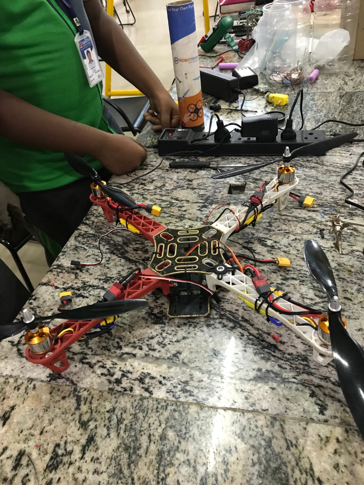
This guide walks through building a fully functional quadcopter from individual components, with flight control managed by the dedicated KK2.1.5 flight controller. The platform uses four brushless motors driven by 40 A ESCs, powered by a 3S LiPo battery through a power distribution board, and receives commands from a FlySky-compatible radio receiver.
Builders will receive a complete parts list, wiring diagrams for the power system and flight-control integration, and step-by-step assembly instructions organized across mechanical integration, propulsion setup, power distribution, flight-controller configuration, and radio-control binding. The modular design makes it straightforward to upgrade individual components like motors or ESCs as skills develop.
Wiring diagram

Gather all the parts
Assemble it in 6 steps
1. Stage 1 — Mechanical Integration
The Quadcopter Frame provides the mechanical reference for organizing the XT60 Quadcopter Power Distribution Board (PDB), the KK2.1.5 Multi-Rotor Flight Controller, four ESCs, four 2200 KV brushless motors, and the FlySky-compatible 6-channel PWM Receiver. The documented prototype keeps the propulsion assignments fixed: ESC1 → Motor 1, ESC2 → Motor 2, ESC3 → Motor 3, and ESC4 → Motor 4. This stage records the intended engineering organization, not a construction or flight procedure.
- Use the component identifiers consistently in the schematic, connection table, and prototype records.
- This engineering documentation describes system organization only; it does not prove electrical, powered, or flight validation.
2. Stage 2 — Propulsion-System Integration
The propulsion subsystem consists of four 40 A brushless ESCs and four 2200 KV brushless motors. The fixed ESC-to-motor pairings are ESC1 → Motor 1, ESC2 → Motor 2, ESC3 → Motor 3, and ESC4 → Motor 4. For each pair, PHASE A, PHASE B, and PHASE C are documented specifically as MOTOR PHASE connections, separate from the propulsion-power and PWM control-signal paths.
- Keep the ESC and motor identifiers consistent across all engineering records.
- MOTOR PHASE is the required label for all twelve ESC-to-motor phase links; they are not data, digital, PWM, or generic power connections.
3. Stage 3 — Power-System Integration
The prototype’s propulsion-power architecture is documented as 3S 4200 mAh LiPo Battery with XT60 → XT60 Quadcopter Power Distribution Board (PDB) → four ESCs. The battery and PDB define the high-current propulsion-power section, while control electronics are recorded as a separate control-power and signal section. This functional separation supports clear engineering inspection and future revision.
- Review positive and ground paths separately against the connection table during documentation checks.
- High-current LiPo systems require appropriate engineering safety controls; this portfolio record is not a battery-handling procedure.
4. Stage 4 — Flight-Control Integration
The KK2.1.5 Multi-Rotor Flight Controller is the actual flight-control component in this prototype. ESC1 connects to KK2.1.5 M1, ESC2 to M2, ESC3 to M3, and ESC4 to M4 through their corresponding PWM CONTROL SIGNAL and ground paths. ESC1 provides the designated 5 V BEC supply for the documented control system through the KK2.1.5 M1 power connection. No ESP32 is a physical or connected component of this quadcopter.
- Treat M1–M4 as fixed interface identifiers in every design revision.
- This stage records system integration only; it does not include powered testing, calibration, or flight procedures.
5. Stage 5 — Radio-Control Integration
The FlySky-compatible 6-channel PWM Receiver provides the radio-control inputs to the KK2.1.5. Its documented PWM mapping is CH1 → AIL, CH2 → ELE, CH3 → THR, CH4 → RUD, and CH5 → AUX; B/VCC and GND are the receiver power connections. This records PWM control-signal integration and distinguishes receiver inputs from ESC PWM control outputs.
- Compare receiver labels directly with the connection table so channel names remain identical in all records.
- This documentation does not include transmitter configuration, receiver binding, or aircraft-operation instructions.
6. Stage 6 — Engineering Inspection and Documentation
The final engineering review documents component identification, the fixed ESC/motor pairings, propulsion-power organization, control-signal organization, polarity labels, MOTOR PHASE labels, receiver PWM channel mapping, and comparison with the complete connection table. Discrepancies are recorded for troubleshooting and iterative development before the design documentation is revised. Advanced capabilities such as autonomous flight, GPS, telemetry, additional sensors, and other future upgrades are concepts only and are not implemented in this prototype. Engineering Prototype — System Design and Documentation. The development record emphasizes component selection → system integration → troubleshooting → iterative development → documentation → future upgrade potential.
- Use the schematic and complete connection table together as the controlled reference for future engineering iterations.
- This engineering documentation does not itself prove electrical validation, powered validation, or flight validation.
Review all connections
1. Connections between "battery_3s_4200mah" and "ESP32"
2. Connections between "pdb_xt60" and "ESP32"
3. Connections between "esc1" and "ESP32"
4. Connections between "esc2" and "ESP32"
5. Connections between "esc3" and "ESP32"
6. Connections between "esc4" and "ESP32"
7. Connections between "receiver" and "ESP32"
Deploy the firmware
// Self-Made Low-Cost and Easily Upgradable Quadcopter
// Documentation-only firmware stub
//
// The KK2.1.5 is the actual flight controller used in the prototype.
// The KK2.1.5 operates using its own flight-controller firmware.
// This Arduino source is NOT used to control the quadcopter.
//
// This stub intentionally performs no hardware I/O and implements:
// - No motor control
// - No ESC control
// - No flight stabilization
// - No telemetry
// - No GPS
// - No autonomous flight
// - No sensor integration
//
// It is included only to satisfy documentation/project-structure
// requirements where a source-code entry is expected.

void setup() {
    // Intentionally empty — documentation stub only.
}

void loop() {
    // Intentionally empty — documentation stub only.
}
Remix this project
Make it yours in one click
Open a full copy of this project in your own Schematik workspace — diagram, code, parts, and assembly steps included. Swap the sensor, add features, or redesign the whole thing with AI. The author's original stays untouched.
Related projects

Create A Complete Electrical Schematic Esp32 Sma
ESP32 · September 17, 2026Ayansh Agrawal
ESP32 Kare Ekran Projeleri
ESP32 · September 16, 2026Seref Ai
Component Qty --------------------------- ------
ESP32 · September 16, 2026Yathartha Chakrawal