Community project
Smart Energy Monitoring System
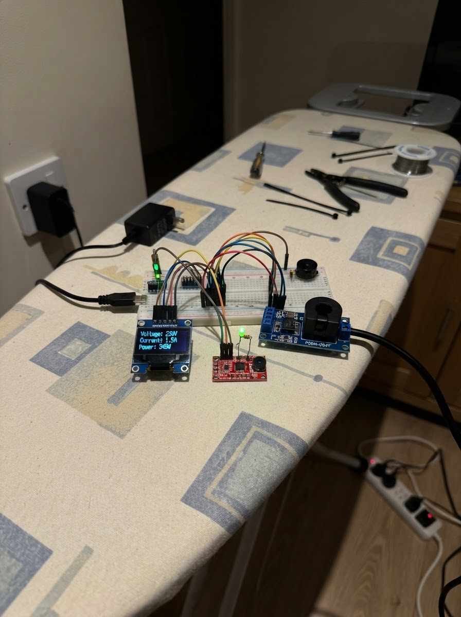
This smart energy monitoring system tracks real-time electrical consumption using a PZEM-004T power meter connected to an ESP32 microcontroller. The system displays voltage, current, power draw, and cumulative energy usage on a small OLED screen, with status indicators via LED and buzzer for system feedback.
The guide provides a complete wiring diagram, parts list, and step-by-step assembly instructions that keep the mains-voltage side safely isolated from the low-voltage control electronics. Builders will receive the full firmware code, component pinout details, and safety guidelines for integrating the meter into their electrical monitoring setup.
Wiring diagram

Gather all the parts
Assemble it in 6 steps
1. Keep the mains side separate
Put the ESP32, OLED, level converter, LED, buzzer, and the low-voltage pins of the PZEM in one insulated low-voltage area. Put the PZEM AC terminals and the appliance wires in a separate closed mains enclosure, with a physical gap between the two areas.
- Use a labelled enclosure or divider marked LOW VOLTAGE CONTROL and HIGH VOLTAGE AC.
- AC mains wiring must be done by qualified electrician. Touching an exposed Live wire can cause fatal electric shock or fire.
2. Power the low-voltage section
Connect the adapter +5V lead to the ESP32 5V/VIN pin and PZEM VCC pin. Connect the adapter GND lead to ESP32 GND and PZEM GND; all low-voltage ground wires must meet. Do not connect the adapter directly to household AC wiring.
- +5V → ESP32 VIN/5V and PZEM VCC (power); GND → ESP32 GND and PZEM GND (ground).
- Make sure the adapter positive and negative leads are not swapped — reversed power can damage the ESP32 or meter.
3. Wire the protected meter data connection
Connect PZEM TX to the level converter HV1 and level converter LV1 to ESP32 GPIO16. Connect ESP32 GPIO17 to level converter LV2 and level converter HV2 to PZEM RX. Power the converter with HV → 5V, LV → ESP32 3.3V, and GND → the shared ground.
- PZEM TX → converter HV1 → GPIO16 (meter data); GPIO17 → converter LV2/HV2 → PZEM RX (meter command); HV → 5V, LV → 3V3, GND → GND (power and ground).
- Do not connect a 5V PZEM TX pin straight to GPIO16 — 5V can damage an ESP32 GPIO pin.
4. Add the small screen
Connect OLED VCC to ESP32 3.3V, OLED GND to ESP32 GND, OLED SDA to GPIO21, and OLED SCL to GPIO22.
- VCC → 3V3 (power); GND → GND (ground); SDA → GPIO21 (data); SCL → GPIO22 (clock).
- Make sure VCC and GND are not swapped — swapped power can damage the screen.
5. Add the status light and buzzer
Connect GPIO4 to one end of the 220 ohm resistor. Connect the resistor's other end to the LED long leg, then connect the LED short leg to GND. Connect buzzer + to GPIO25 and buzzer - to GND.
- GPIO4 → 220 ohm resistor → LED long leg (status signal); LED short leg → GND (ground); buzzer + → GPIO25 (alert signal); buzzer - → GND (ground).
- The resistor must stay in series with the LED — without it, the LED or board pin can be damaged.
6. Have the AC wiring completed safely
A qualified electrician should connect protected AC Live and Neutral to the PZEM voltage input terminals, then route Live and Neutral onward to the labelled load: Freezer / AC / Exhaust Fan. Clip the CT clamp around only the single Live wire that goes from the meter area to that load; do not put Neutral or the whole cable inside the clamp.
- AC Live → PZEM AC-L → load Live (mains measurement); AC Neutral → PZEM AC-N → load Neutral (mains return); CT clamp around only the outgoing Live conductor (current measurement).
- Do not work on energized wires. Putting both Live and Neutral through the CT clamp makes the current reading incorrect, and exposed mains terminals can cause fatal shock or fire.
Review all connections
1. Connections between "adapter_5v_1" and "ESP32"
2. Connections between "pzem_004t_1" and "ESP32"
3. Connections between "level_shifter_1" and "ESP32"
4. Connections between "oled_1" and "ESP32"
5. Connections between "resistor_1" and "ESP32"
6. Connections between "led_1" and "ESP32"
7. Connections between "buzzer_1" and "ESP32"
Deploy the firmware
#include <Arduino.h>
#include <Wire.h>
#include <PZEM004Tv30.h>
#include <Adafruit_GFX.h>
#include <Adafruit_SSD1306.h>


// Forward declarations
void showReadings();
void readMeter();

constexpr int PZEM_RX_PIN = 16;
constexpr int PZEM_TX_PIN = 17;
constexpr int OLED_SDA_PIN = 21;
constexpr int OLED_SCL_PIN = 22;
constexpr int STATUS_LED_PIN = 4;
constexpr int BUZZER_PIN = 25;
constexpr uint8_t OLED_ADDRESS = 0x3C;
constexpr unsigned long READ_INTERVAL_MS = 2000;

PZEM004Tv30 pzem(Serial2, PZEM_RX_PIN, PZEM_TX_PIN);
Adafruit_SSD1306 display(128, 64, &Wire, -1);

float lastVoltage = NAN;
float lastCurrent = NAN;
float lastPower = NAN;
float lastEnergy = NAN;
bool meterOk = false;
bool oledReady = false;
unsigned long lastReadMs = 0;

void showReadings() {
  if (!oledReady) return;

  display.clearDisplay();
  display.setTextColor(SSD1306_WHITE);
  display.setTextSize(1);
  display.setCursor(0, 0);
  display.println("Lynqraj Energy Lab");
  display.drawFastHLine(0, 10, 128, SSD1306_WHITE);

  if (!meterOk) {
    display.setCursor(0, 20);
    display.println("PZEM not responding");
    display.println("Check meter power");
    display.println("and UART wiring.");
  } else {
    display.setCursor(0, 15);
    display.printf("Voltage: %.1f V\n", lastVoltage);
    display.printf("Current: %.2f A\n", lastCurrent);
    display.printf("Power:   %.0f W\n", lastPower);
    display.printf("Energy:  %.3f kWh", lastEnergy);
  }
  display.display();
}

void readMeter() {
  lastVoltage = pzem.voltage();
  lastCurrent = pzem.current();
  lastPower = pzem.power();
  lastEnergy = pzem.energy();
  meterOk = !isnan(lastVoltage) && !isnan(lastCurrent) && !isnan(lastPower) && !isnan(lastEnergy);

  digitalWrite(STATUS_LED_PIN, meterOk ? HIGH : LOW);
  digitalWrite(BUZZER_PIN, meterOk ? LOW : HIGH);

  if (meterOk) {
    Serial.printf("Voltage %.1f V | Current %.2f A | Power %.0f W | Energy %.3f kWh\n", lastVoltage, lastCurrent, lastPower, lastEnergy);
  } else {
    Serial.println("PZEM read failed. Check 5V power, common GND, level converter, and AC input.");
  }
  showReadings();
}

void setup() {
  pinMode(STATUS_LED_PIN, OUTPUT);
  pinMode(BUZZER_PIN, OUTPUT);
  digitalWrite(STATUS_LED_PIN, LOW);
  digitalWrite(BUZZER_PIN, LOW);

  Serial.begin(115200);
  Wire.begin(OLED_SDA_PIN, OLED_SCL_PIN);
  oledReady = display.begin(SSD1306_SWITCHCAPVCC, OLED_ADDRESS);
  if (!oledReady) Serial.println("OLED not found; monitoring continues over serial.");
  readMeter();
}

void loop() {
  if (millis() - lastReadMs >= READ_INTERVAL_MS) {
    lastReadMs = millis();
    readMeter();
  }
}
Remix this project
Make it yours in one click
Open a full copy of this project in your own Schematik workspace — diagram, code, parts, and assembly steps included. Swap the sensor, add features, or redesign the whole thing with AI. The author's original stays untouched.