Community project
Smart Following Suitcase
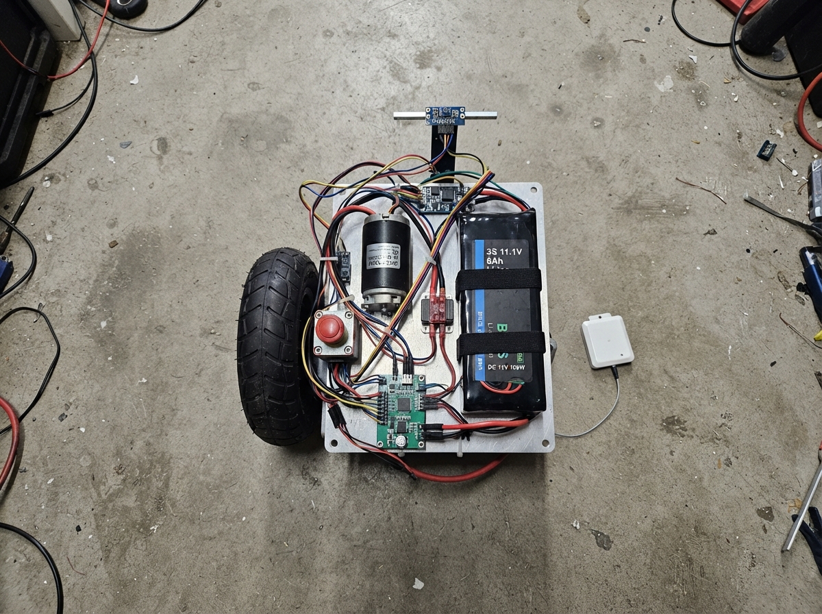
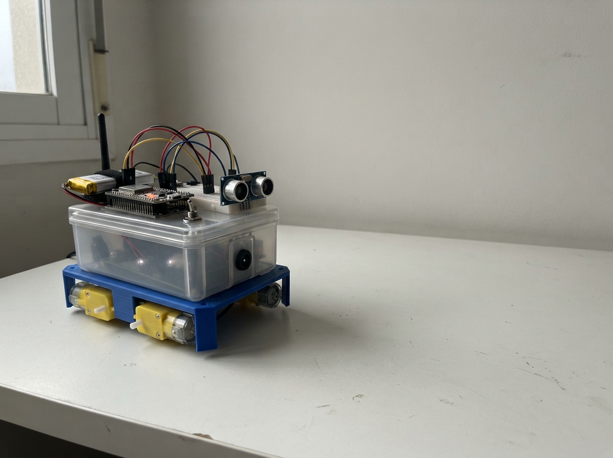
This smart following suitcase uses ultra-wideband (UWB) positioning and time-of-flight sensors to autonomously track and follow a person carrying a UWB tag. The suitcase maintains a safe following distance while detecting obstacles and drop-offs, making it ideal for hands-free luggage transport at airports, events, or during travel.
Built around an ESP32 microcontroller, the suitcase combines a VL53L0X ToF sensor for obstacle detection, dual motor control via an IBT-2 H-bridge driver, and UWB localization for accurate person tracking. This guide provides the complete wiring diagram, parts list, firmware code, and step-by-step assembly instructions to build your own autonomous follower.
Wiring diagram

Gather all the parts
Assemble it in 5 steps
1. Monta una base estable
Fija left_motor y right_motor en un bastidor bajo y ancho con dos ruedas locas traseras. Deja battery_pack bajo, entre los ejes, y prueba la estabilidad con 25 kg de peso simulado antes de alimentar el sistema.
- No pruebes en pendientes ni cerca de personas: una valija cargada puede golpear o caer.
2. Instala el corte de emergencia
Pon main_fuse a menos de 15 cm de battery_pack y emergency_stop donde puedas pulsarlo desde arriba. Conecta el positivo por fusible y paro a ambos controladores; usa cable flexible de potencia de al menos 14 AWG.
- Un cable de batería sin fusible puede calentarse e incendiarse si se aplasta o se pela.
3. Ajusta las tensiones antes de conectar
Ajusta logic_buck a exactamente 5,0 V con un multímetro. Alimenta los puentes H y los dos buffers de PWM con 5V (power). El ESP32, los dos sensores ToF y uwb_anchor usan su rail de 3,3 V (power); todos los GND van juntos (ground).
- No conectes los 11,1 V de la batería al ESP32, al UWB ni a los sensores: se dañarán.
4. Conecta señales y sensores
Conecta los buffers entre el ESP32 y los puentes: GPIO25 y GPIO26 a las entradas del buffer izquierdo, y sus salidas a RPWM y LPWM del puente izquierdo; GPIO13 y GPIO14 hacen lo mismo a la derecha. Para ambos sensores: SDA → GPIO21 (data), SCL → GPIO22 (data); XSHUT frontal → GPIO27 (signal) y XSHUT inferior → GPIO32 (signal). Conecta TX de uwb_anchor → GPIO16 (signal).
- Monta el sensor frontal a 20–30 cm del suelo y el inferior a 10–15 cm, apuntando un poco hacia delante.
- No cubras las ventanas de los sensores: si no ven correctamente, la valija se detiene por seguridad.
5. Prueba primero con las ruedas elevadas
Con las ruedas motrices sobre soportes firmes, carga uwb_tag, inserta el fusible y libera emergency_stop. Comprueba que al apagar la etiqueta, tapar un sensor o pulsar el botón rojo los motores se detienen. Después haz pruebas lentas en un pasillo vacío.
- Nunca la pruebes cerca de escaleras, bordillos, mascotas, personas o tráfico; el paro físico es la protección principal.
Review all connections
1. Connections between "battery_pack" and "ESP32"
2. Connections between "main_fuse" and "ESP32"
3. Connections between "emergency_stop" and "ESP32"
4. Connections between "logic_buck" and "ESP32"
5. Connections between "motor_driver_left" and "ESP32"
6. Connections between "motor_driver_right" and "ESP32"
7. Connections between "tof_front" and "ESP32"
8. Connections between "tof_drop" and "ESP32"
9. Connections between "uwb_anchor" and "ESP32"
10. Connections between "uwb_tag" and "ESP32"
11. Connections between "left_pwm_buffer" and "ESP32"
12. Connections between "right_pwm_buffer" and "ESP32"
Deploy the firmware
#include <Arduino.h>
#include <Wire.h>
#include <Adafruit_VL53L0X.h>

constexpr int LEFT_FWD_PIN = 25;
constexpr int LEFT_REV_PIN = 26;
constexpr int RIGHT_FWD_PIN = 13;
constexpr int RIGHT_REV_PIN = 14;
constexpr int FRONT_XSHUT_PIN = 27;
constexpr int DROP_XSHUT_PIN = 32;
constexpr int UWB_RX_PIN = 16;
constexpr int I2C_SDA_PIN = 21;
constexpr int I2C_SCL_PIN = 22;

constexpr uint16_t PWM_HZ = 20000;
constexpr uint8_t PWM_BITS = 8;
constexpr int CRUISE_PWM = 72;
constexpr int FOLLOW_STOP_CM = 130;
constexpr int FRONT_STOP_MM = 650;
constexpr int DROP_STOP_MM = 300;
constexpr uint32_t UWB_TIMEOUT_MS = 350;
constexpr uint32_t SENSOR_INTERVAL_MS = 60;

Adafruit_VL53L0X frontSensor;
Adafruit_VL53L0X dropSensor;
bool frontReady = false;
bool dropReady = false;
int frontMm = 8190;
int dropMm = 0;
float uwbDistanceCm = 0.0f;
float uwbBearingDeg = 0.0f;
uint32_t lastUwbMs = 0;
uint32_t lastSensorMs = 0;
String uwbLine;

void setMotorChannels(int leftForward, int leftReverse, int rightForward, int rightReverse) {
  ledcWrite(LEFT_FWD_PIN, constrain(leftForward, 0, 255));
  ledcWrite(LEFT_REV_PIN, constrain(leftReverse, 0, 255));
  ledcWrite(RIGHT_FWD_PIN, constrain(rightForward, 0, 255));
  ledcWrite(RIGHT_REV_PIN, constrain(rightReverse, 0, 255));
}

void stopMotors() { setMotorChannels(0, 0, 0, 0); }

bool readDistance(Adafruit_VL53L0X &sensor, int &millimeters) {
  VL53L0X_RangingMeasurementData_t measurement;
  sensor.rangingTest(&measurement, false);
  if (measurement.RangeStatus == 4) return false;
  millimeters = measurement.RangeMilliMeter;
  return true;
}

void updateSensors() {
  if (millis() - lastSensorMs < SENSOR_INTERVAL_MS) return;
  lastSensorMs = millis();
  int value;
  if (frontReady && readDistance(frontSensor, value)) frontMm = value;
  if (dropReady && readDistance(dropSensor, value)) dropMm = value;
}

void parseUwbLine(const String &line) {
  // Configure the UWB UART bridge to emit: $UWB,<distance_cm>,<bearing_deg>\n
  if (!line.startsWith("$UWB,")) return;
  int comma = line.indexOf(',', 5);
  if (comma < 0) return;
  float distance = line.substring(5, comma).toFloat();
  float bearing = line.substring(comma + 1).toFloat();
  if (distance < 20.0f || distance > 3000.0f || bearing < -180.0f || bearing > 180.0f) return;
  uwbDistanceCm = distance;
  uwbBearingDeg = bearing;
  lastUwbMs = millis();
}

void readUwb() {
  while (Serial2.available()) {
    char c = static_cast<char>(Serial2.read());
    if (c == '\n' || c == '\r') {
      if (uwbLine.length() > 0) parseUwbLine(uwbLine);
      uwbLine = "";
    } else if (uwbLine.length() < 63) {
      uwbLine += c;
    } else {
      uwbLine = "";
    }
  }
}

bool safetyClear() {
  if (!frontReady || !dropReady) return false;
  if (frontMm < FRONT_STOP_MM) return false;
  // A much larger down-facing reading means a curb, step, or hole.
  if (dropMm <= 0 || dropMm > DROP_STOP_MM) return false;
  return true;
}

void followTag() {
  if (!safetyClear() || millis() - lastUwbMs > UWB_TIMEOUT_MS || uwbDistanceCm <= FOLLOW_STOP_CM) {
    stopMotors();
    return;
  }
  // Turn toward the wearer before advancing; reverse is never commanded.
  if (uwbBearingDeg > 18.0f) {
    setMotorChannels(CRUISE_PWM, 0, 0, 0);
  } else if (uwbBearingDeg < -18.0f) {
    setMotorChannels(0, 0, CRUISE_PWM, 0);
  } else {
    int correction = constrain(static_cast<int>(uwbBearingDeg * 1.2f), -28, 28);
    setMotorChannels(CRUISE_PWM - correction, 0, CRUISE_PWM + correction, 0);
  }
}

void setupTofSensors() {
  pinMode(FRONT_XSHUT_PIN, OUTPUT);
  pinMode(DROP_XSHUT_PIN, OUTPUT);
  digitalWrite(FRONT_XSHUT_PIN, LOW);
  digitalWrite(DROP_XSHUT_PIN, LOW);
  delay(20);
  digitalWrite(FRONT_XSHUT_PIN, HIGH);
  delay(20);
  frontReady = frontSensor.begin(0x29, false, &Wire);
  if (frontReady) frontSensor.setAddress(0x30);
  digitalWrite(DROP_XSHUT_PIN, HIGH);
  delay(20);
  dropReady = dropSensor.begin(0x29, false, &Wire);
  if (dropReady) dropSensor.setAddress(0x31);
}

void setup() {
  Serial.begin(115200);
  Serial2.begin(115200, SERIAL_8N1, UWB_RX_PIN, -1);
  Wire.begin(I2C_SDA_PIN, I2C_SCL_PIN);
  ledcAttach(LEFT_FWD_PIN, PWM_HZ, PWM_BITS);
  ledcAttach(LEFT_REV_PIN, PWM_HZ, PWM_BITS);
  ledcAttach(RIGHT_FWD_PIN, PWM_HZ, PWM_BITS);
  ledcAttach(RIGHT_REV_PIN, PWM_HZ, PWM_BITS);
  stopMotors();
  setupTofSensors();
}

void loop() {
  readUwb();
  updateSensors();
  followTag();
  delay(10);
}
Remix this project
Make it yours in one click
Open a full copy of this project in your own Schematik workspace, diagram, code, parts, and assembly steps included. Swap the sensor, add features, or redesign the whole thing with AI. The author's original stays untouched.