Community project
Smart Gate Lock Camera
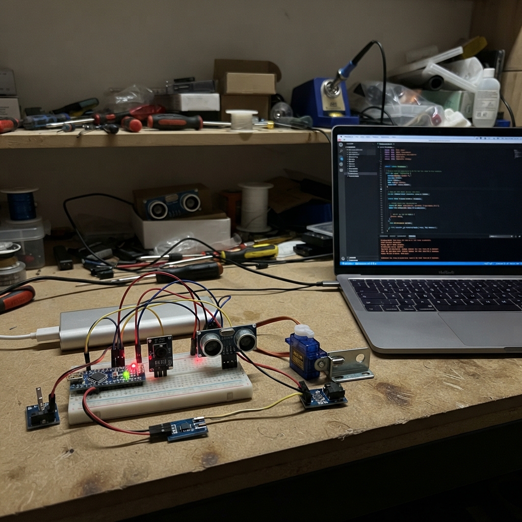
This smart gate lock camera combines an ESP32-CAM with dual servo motors, proximity sensing, and vibration detection to create a remotely monitored gate access system. The build integrates an ultrasonic distance sensor, reed switch for gate position, vibration alarm, and dual limit switches to track lock mechanism state—all controlled by an ESP32 microcontroller that captures video and logs access events.
The guide provides a complete wiring diagram, parts list, and step-by-step assembly instructions for integrating the servo actuators, sensors, and camera module. Firmware is included to manage multiple operating modes (home, night, away, alarm, smoke), handle deadlock engagement, and trigger the camera on motion or unauthorized access attempts.
Wiring diagram

Gather all the parts
Assemble it in 6 steps
1. Make the common ground rail
Use one breadboard ground rail for the lock controller side. Connect a WeAct GND pin to it, then connect the negative output of the servo MB102, the negative output of the camera MB102, both servo brown/black wires, the HC-SR04 GND pin, every switch common pin, both LED short legs, the capacitor striped leg, and ESP32-CAM GND to that same rail. This shared ground lets the two boards understand the trigger signal safely.
- Use thicker short wires for the two servo power and ground connections.
- Do not join the two 5 V positive rails together; only join their grounds. Swapped power or a missing shared ground can reset boards or damage parts.
2. Power the lock controller and actuator rail
Power the WeAct ESP32-C6-MiNi only from its USB-C port. Set the first MB102 module to 5 V and feed it from its own regulated 5 V, 2 A adapter. Connect its 5 V rail to both servo red wires, HC-SR04 VCC, and the long positive lead of the 470 µF capacitor; connect its ground rail to the common ground rail.
- Check the MB102 output with a meter before inserting the servo plugs.
- Never connect the MB102 5 V rail to the WeAct 3V3 pin. Never power either servo from the WeAct board. The capacitor stripe must go to ground; reversing it can make it fail.
3. Wire the lock controller signals
Connect pawl-servo signal to GPIO18 (movement signal) and deadlock-servo signal to GPIO19 (movement signal). Connect HC-SR04 TRIG to GPIO20 (distance-start signal). Run HC-SR04 ECHO through the 1 kΩ resistor, then use that resistor junction for GPIO21 and connect a 2 kΩ resistor from the same junction to ground; this drops the 5 V echo pulse to about 3.3 V. Connect MC-38 one wire to GPIO10 and the other to ground (gate-shut signal). Connect hook limit NO to GPIO3 and COM to ground (hook-home signal); connect inside-lever limit NO to GPIO11 and COM to ground (inside-release signal).
- For the HC-SR04 divider, GPIO21 must touch only the junction between the two resistors, not the raw ECHO pin.
- Raw HC-SR04 ECHO is 5 V and will damage the 3.3 V-only ESP32-C6 input if connected directly to GPIO21.
4. Add vibration sensor and lock lights
Connect SW-420 VCC to WeAct 3V3, GND to the common ground rail, and DO to GPIO2 (shaking signal). Connect GPIO6 through its own 330 Ω resistor to the long leg of the green LED, then connect the LED short leg to ground (unlocked light). Connect GPIO7 through its own 330 Ω resistor to the long leg of the red LED, then connect the LED short leg to ground (locked light).
- If vibration events occur continuously while the gate is still, turn the small SW-420 adjustment screw slowly until only a firm shake changes its output.
- Do not power the SW-420 from 5 V in this design because its DO output could then rise to 5 V and damage GPIO2. Each LED needs its own 330 Ω resistor; without one the LED or board output can be damaged.
5. Wire and power the camera board
Put the ESP32-CAM into its own breadboard area and power its 5V pin from a second MB102 set to 5 V and fed by a separate regulated 5 V, 2 A adapter. Connect its GND to the common ground rail. Connect WeAct GPIO22 directly to ESP32-CAM GPIO13 (3.3 V trigger signal). Leave the SD-card socket unused so GPIO13 remains available.
- Use the ESP32-CAM-MB only for programming the camera board; remove it or power the camera from its dedicated 5 V supply for the gate test.
- Do not power the ESP32-CAM from the WeAct 3V3 pin. Do not attach a microSD card while using GPIO13 as the trigger input.
6. Check movement before fitting the lock mechanism
With the servo horns not yet attached to the gate linkage, power the boards and test each servo's full movement. Fit the pawl horn so 0 degrees means the pawl is down and locked, and fit the deadlock horn so 0 degrees is free and 90 degrees is deadlocked.
- Mount the servo horn only after confirming the startup positions, so the mechanism cannot bind.
- Keep fingers clear of the servo arms. A mechanically jammed servo can draw enough current to heat wires or reset the controller.
Review all connections
1. Connections between "servo_pawl" and "ESP32"
2. Connections between "servo_deadlock" and "ESP32"
3. Connections between "ultrasonic_gate" and "ESP32"
4. Connections between "echo_resistor_high" and "ESP32"
5. Connections between "echo_resistor_low" and "ESP32"
6. Connections between "reed_gate_shut" and "ESP32"
7. Connections between "vibration_gate" and "ESP32"
8. Connections between "limit_hook_home" and "ESP32"
9. Connections between "limit_inside_lever" and "ESP32"
10. Connections between "resistor_green_led" and "ESP32"
11. Connections between "led_unlocked" and "ESP32"
12. Connections between "resistor_red_led" and "ESP32"
13. Connections between "led_locked" and "ESP32"
14. Connections between "servo_bulk_capacitor" and "ESP32"
15. Connections between "camera_gate" and "ESP32"
Deploy the firmware
#include <Arduino.h>
#include <ESP32Servo.h>
#include "thread_stubs.h"

constexpr uint8_t PAWL_SERVO_PIN=18, DEADLOCK_SERVO_PIN=19, ULTRASONIC_TRIG_PIN=20, ULTRASONIC_ECHO_PIN=21;
constexpr uint8_t GATE_REED_PIN=10, VIBRATION_PIN=2, HOOK_HOME_PIN=3, INSIDE_LEVER_PIN=11;
constexpr uint8_t CAMERA_TRIGGER_PIN=22, GREEN_LED_PIN=6, RED_LED_PIN=7;
#define SW420_ACTIVE_LEVEL HIGH // Change to LOW for an inverted SW-420 module.
constexpr uint32_t RELEASE_MS=5000, PRESENCE_MS=1000, PULSE_MS=200, SENSOR_MS=100, DEBOUNCE_MS=150;
Servo pawl, deadlockServo;
enum Mode { HOME, NIGHT, AWAY, ALARM, SMOKE }; Mode mode=HOME;
bool isDeadlocked=false, released=false; uint32_t releaseUntil=0, cameraUntil=0, presenceSince=0, lastSensor=0, lastVibration=0, lastLever=0;
String lastEvent="boot";

const char* modeName(){ static const char* names[]={"home","night","away","alarm","smoke"}; return names[mode]; }
bool closed(uint8_t pin){ return digitalRead(pin)==LOW; }
void move(Servo &s,uint8_t pin,int degrees){ s.setPeriodHertz(50); s.attach(pin,500,2400); s.write(degrees); delay(650); s.detach(); }
void event(const char* e){ lastEvent=e; sendEvent(e); }
void setDeadlock(bool on){ if(isDeadlocked==on)return; move(deadlockServo,DEADLOCK_SERVO_PIN,on?90:0); isDeadlocked=on; event(on?"deadlocked":"free"); }
void releasePawl(const char* why){ if(isDeadlocked){ event("release_ignored_deadlocked"); return; } if(!released) move(pawl,PAWL_SERVO_PIN,90); released=true; releaseUntil=millis()+RELEASE_MS; if(why) event(why); }
void lockPawl(const char* why=nullptr){ if(!released)return; move(pawl,PAWL_SERVO_PIN,0); released=false; releaseUntil=0; if(why) event(why); }
void triggerCamera(const char* why){ digitalWrite(CAMERA_TRIGGER_PIN,HIGH); cameraUntil=millis()+PULSE_MS; event(why); }
float distanceCm(){ digitalWrite(ULTRASONIC_TRIG_PIN,LOW); delayMicroseconds(3); digitalWrite(ULTRASONIC_TRIG_PIN,HIGH); delayMicroseconds(10); digitalWrite(ULTRASONIC_TRIG_PIN,LOW); uint32_t us=pulseIn(ULTRASONIC_ECHO_PIN,HIGH,30000); return us?us/58.0f:-1; }
String stateText(){ return "gate_shut="+String(closed(GATE_REED_PIN)?"true":"false")+", hook_home="+String(closed(HOOK_HOME_PIN)?"true":"false")+", deadlock="+String(isDeadlocked?"true":"false")+", last_event="+lastEvent; }
void report(){ Serial.println(getState()); }
void setModeFromText(const String &raw){ String m=raw; m.toLowerCase(); if(m=="home")mode=HOME; else if(m=="night")mode=NIGHT; else if(m=="away")mode=AWAY; else if(m=="alarm")mode=ALARM; else if(m=="smoke")mode=SMOKE; else {Serial.println("Modes: home, night, away, alarm, smoke");return;} if(mode==AWAY||mode==ALARM){lockPawl();setDeadlock(true);} else if(mode==SMOKE){setDeadlock(false);releasePawl("smoke_release");} else setDeadlock(false); event((String("mode_")+modeName()).c_str()); report(); }
void handleCommand(const String &raw){ String c=raw; c.trim();c.toLowerCase(); if(c=="release"){if(mode==AWAY||mode==ALARM)event("release_ignored_mode");else releasePawl("electric_release");} else if(c=="deadlock"){lockPawl();setDeadlock(true);} else if(c=="free")setDeadlock(false); else if(c=="state")report(); else Serial.println("Commands: release, deadlock, free, state"); }
void serialSimulator(){ if(!Serial.available())return; String x=Serial.readStringUntil('\n');x.trim(); if(x.startsWith("mode "))onMode(x.substring(5).c_str());else if(x.startsWith("cmd "))onCommand(x.substring(4).c_str());else if(x=="state")report(); }
void setup(){ Serial.begin(115200); pinMode(GATE_REED_PIN,INPUT_PULLUP);pinMode(HOOK_HOME_PIN,INPUT_PULLUP);pinMode(INSIDE_LEVER_PIN,INPUT_PULLUP);pinMode(VIBRATION_PIN,INPUT);pinMode(ULTRASONIC_TRIG_PIN,OUTPUT);pinMode(ULTRASONIC_ECHO_PIN,INPUT);pinMode(CAMERA_TRIGGER_PIN,OUTPUT);pinMode(GREEN_LED_PIN,OUTPUT);pinMode(RED_LED_PIN,OUTPUT);digitalWrite(CAMERA_TRIGGER_PIN,LOW); move(pawl,PAWL_SERVO_PIN,0);move(deadlockServo,DEADLOCK_SERVO_PIN,0);Serial.println("Gate lock ready: mode away | cmd release | state");report(); }
void loop(){ uint32_t now=millis();serialSimulator(); if(cameraUntil&&now>=cameraUntil){digitalWrite(CAMERA_TRIGGER_PIN,LOW);cameraUntil=0;} if(released&&now>=releaseUntil)lockPawl("release_timeout_locked"); if(digitalRead(VIBRATION_PIN)==SW420_ACTIVE_LEVEL&&now-lastVibration>DEBOUNCE_MS){lastVibration=now;triggerCamera("forced");} if(closed(INSIDE_LEVER_PIN)&&now-lastLever>DEBOUNCE_MS){lastLever=now;if(mode!=AWAY&&mode!=ALARM&&!isDeadlocked)releasePawl("manual_release");else event("manual_release_ignored");} if(now-lastSensor>=SENSOR_MS){lastSensor=now;float cm=distanceCm();if(cm>0&&cm<150){if(!presenceSince)presenceSince=now;if(now-presenceSince>=PRESENCE_MS&&!cameraUntil){triggerCamera("at_gate");presenceSince=now;}}else presenceSince=0;} digitalWrite(GREEN_LED_PIN,released);digitalWrite(RED_LED_PIN,!released); }
Remix this project
Make it yours in one click
Open a full copy of this project in your own Schematik workspace — diagram, code, parts, and assembly steps included. Swap the sensor, add features, or redesign the whole thing with AI. The author's original stays untouched.