Community project
Smart Infrastructure Monitoring Box
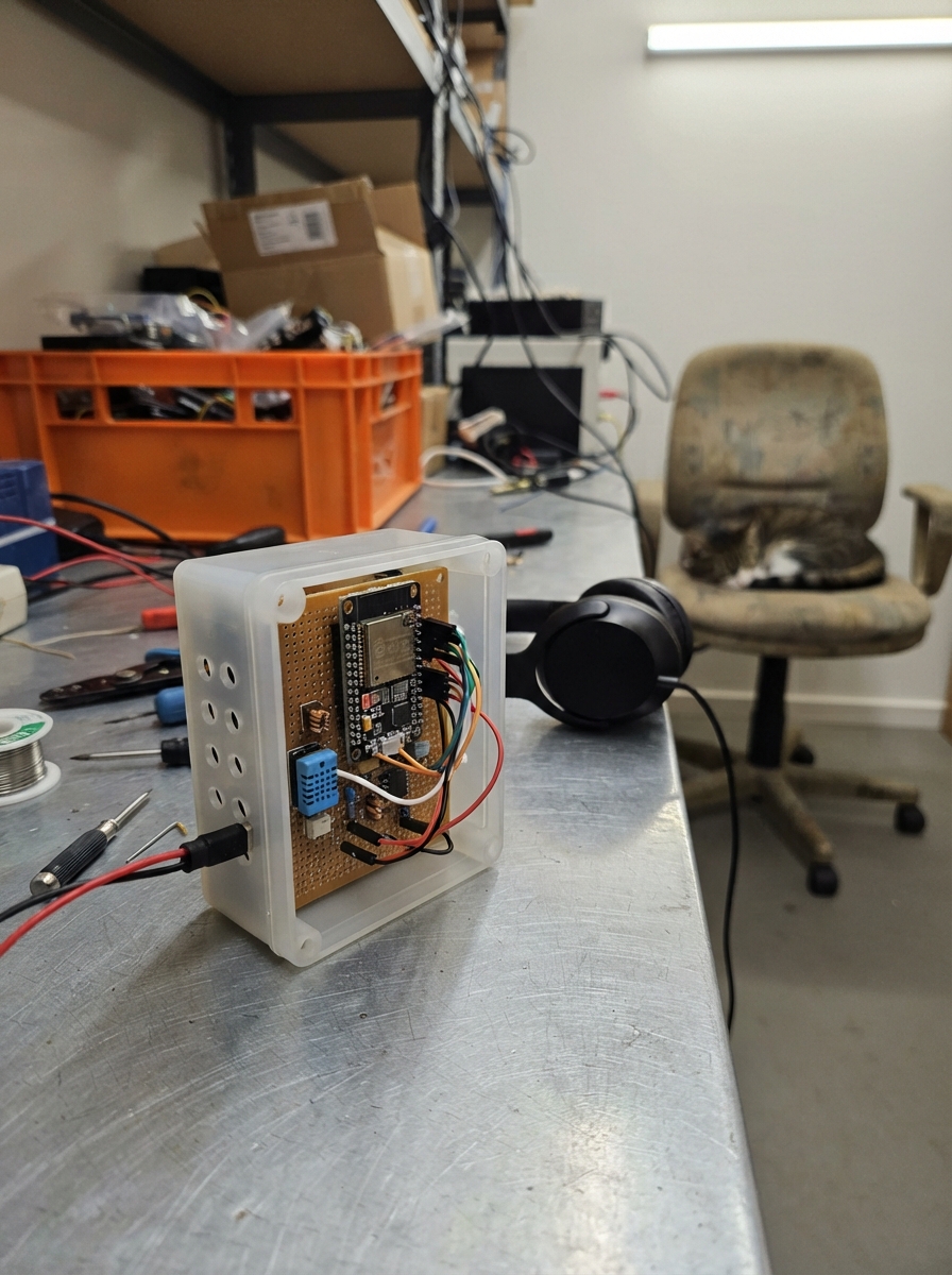
This project builds a networked monitoring box that tracks environmental conditions and infrastructure health using an ESP32 microcontroller. The device measures temperature and humidity with a Sensirion SHT31 sensor, monitors connectivity to multiple network targets, and reports status changes via webhook notifications. Builders will receive a complete four-layer PCB layout, a detailed parts list with bare components, step-by-step assembly instructions starting with power validation, and Arduino firmware that handles Wi-Fi connectivity, sensor polling, and event logging.
The guide covers the full development cycle from schematic review through first-article validation, including guidance on configuring Wi-Fi credentials, webhook endpoints, and monitoring targets before deployment. The firmware implements a robust event queue, latency measurement, and downtime tracking—making this suitable for data center, facility, or remote site supervision where rapid alerting on environmental or network changes is critical.
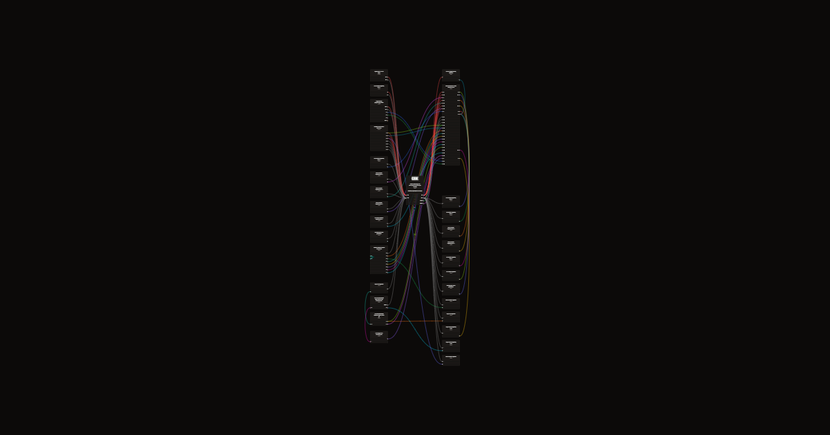
Wiring diagram
Gather all the parts
Assemble it in 5 steps
1. Engineering review before ordering
This is a bare-chip electrical prototype specification, NOT a routed PCB or manufacturing package. Have your PCB engineer create CAD schematic, footprints, placement, Gerbers, drill, BOM and pick-and-place files. Audit all pin numbers against selected package datasheets. Use Espressif ESP32 schematic and layout guidelines. No development board or sensor breakout is used.
- Do not send this connection list directly to an assembly factory as production-ready.
2. Lay out the four-layer PCB
Use signal / uninterrupted ground / power / signal layers. Ground exposed chip pad with thermal vias. Keep flash short. Place each bypass capacitor at its pin. Route RF to SMA at 50 ohms using the actual stackup; keep matching 0201 parts against LNA_IN and ground vias adjacent. Place crystal at least 2.7 mm from chip clock pins as manufacturer recommends, with no trace vias. Place sensor at vented edge on thermally isolated region, away from processor heat. No conformal coating or flux residue on sensor opening.
3. Assemble and check power first
Professional reflow for QFN and DFN; inspect exposed-pad joints. Initially use a current-limited bench source at J1: POS=3.3 V, NEG=GND. Check for shorts before power. Verify all supply domains including VDD_SDIO and delayed CHIP_PU rise; Wi-Fi bursts must not pull rails below operating range. Fit antenna before enabling radio.
- 5 V at J1 or any UART signal can destroy the chips. Do not connect mains or UPS terminals.
4. Program the first article
Use the six-pad header with a 3.3 V USB-UART factory tool: GND common, board TX to tool RX, board RX to tool TX. VREF is sense only. Supply board at J1; do not power it from the UART tool. Hold BOOT low, pulse EN low, release EN and then BOOT to enter serial download. After programming pulse EN with BOOT released for normal operation.
5. Validate before production
RF engineer must tune CLC network and crystal loads on assembled board, measure Wi-Fi range, frequency error, harmonics and antenna match with enclosure. Component RF values are starting points, not guaranteed production values. Verify sensor accuracy, network outages, power cycling and queued alerts. Obtain applicable radio, EMC and product safety approvals before commercial sale; bare chips do not provide module certification. Current firmware remains Wi-Fi-only and still needs the external alert/subscription backend.
- Not production released; no Ethernet, UPS isolation circuitry, onboard USB or persistent outage history is added by this revision.
Review all connections
1. Connections between "power_in" and "ESP32"
2. Connections between "soc" and "ESP32"
3. Connections between "rf_supply_l" and "ESP32"
4. Connections between "bulk" and "ESP32"
5. Connections between "rf_bulk" and "ESP32"
6. Connections between "rf_bulk2" and "ESP32"
7. Connections between "rf_dec" and "ESP32"
8. Connections between "analog1" and "ESP32"
9. Connections between "rtc_dec" and "ESP32"
10. Connections between "cpu_dec" and "ESP32"
11. Connections between "analog43" and "ESP32"
12. Connections between "analog46" and "ESP32"
13. Connections between "sdio_dec" and "ESP32"
14. Connections between "cap1" and "ESP32"
15. Connections between "enable_r" and "ESP32"
16. Connections between "enable_c" and "ESP32"
17. Connections between "reset" and "ESP32"
18. Connections between "boot_r" and "ESP32"
19. Connections between "boot" and "ESP32"
20. Connections between "strap12" and "ESP32"
21. Connections between "strap2" and "ESP32"
22. Connections between "flash" and "ESP32"
23. Connections between "flash_r1" and "ESP32"
24. Connections between "flash_r2" and "ESP32"
25. Connections between "flash_r3" and "ESP32"
26. Connections between "flash_r5" and "ESP32"
27. Connections between "flash_r6" and "ESP32"
28. Connections between "flash_r7" and "ESP32"
29. Connections between "flash_dec" and "ESP32"
30. Connections between "flash_cs_pull" and "ESP32"
31. Connections between "xtal_series" and "ESP32"
32. Connections between "crystal" and "ESP32"
33. Connections between "xtal_c1" and "ESP32"
34. Connections between "xtal_c2" and "ESP32"
35. Connections between "rf_c1" and "ESP32"
36. Connections between "rf_l" and "ESP32"
37. Connections between "rf_c2" and "ESP32"
38. Connections between "antenna" and "ESP32"
39. Connections between "environment" and "ESP32"
40. Connections between "sda_pull" and "ESP32"
41. Connections between "scl_pull" and "ESP32"
42. Connections between "sensor_dec" and "ESP32"
43. Connections between "program" and "ESP32"
Deploy the firmware
// Bare ESP32-D0WD-V3 PCB: external 4 MB flash, 40 MHz crystal.
// SHT31-DIS at 0x44; SDA=GPIO21 (U1 pad42), SCL=GPIO22 (U1 pad39).
#include <Arduino.h>
#include <WiFi.h>
#include <WebServer.h>
#include <HTTPClient.h>
#include <WiFiClientSecure.h>
#include <Wire.h>
#include <Adafruit_SHT31.h>
#include <time.h>
// Set these before Deploy. Use a dedicated monitoring Wi-Fi network.
const char* SSID="YOUR_WIFI";
const char* PASSWORD="YOUR_WIFI_PASSWORD";
const char* DASH_PASSWORD="CHANGE_THIS_PASSWORD";
const char* WEBHOOK=""; // HTTPS endpoint accepting JSON {"text":"..."}
const char* WEBHOOK_CA=""; // PEM root CA for webhook host; never bypass TLS validation.
const char* BEARER="";
const char* UPS_URL=""; // Optional trusted LAN HTTP gateway: 200 + ONLINE or ONBATT
struct Target {const char* name; const char* host; uint16_t port; bool known=false,up=false; uint8_t failures=0; uint32_t downAt=0; uint64_t downtime=0; int latency=-1;};
// Replace empty hosts with local IPs. TCP reachability is not CPU/port/SNMP health.
Target targets[]={{"Internet A","1.1.1.1",443},{"Internet B","8.8.8.8",443},{"Router","",80},{"Switch","",443},{"Server","",443},{"Firewall","",443}};
WebServer server(80);
Adafruit_SHT31 sensor;
float temp=NAN, humidity=NAN;
String events[40]; unsigned eventIndex=0;
String pending[24]; unsigned qhead=0,qcount=0; uint32_t dropped=0;
uint32_t lastPoll=0,lastSend=0; bool sensorOK=false; int environmentState=-1, internetState=-1; String upsState="disabled";
String stamp(){time_t now=time(nullptr); if(now<1700000000) return String("uptime ")+String(millis()/1000)+"s"; char b[32]; struct tm t; gmtime_r(&now,&t); strftime(b,sizeof(b),"%Y-%m-%dT%H:%M:%SZ",&t); return b;}
String escape(String s){s.replace("\\","\\\\");s.replace("\"","\\\"");s.replace("\n","\\n");s.replace("\r","");return s;}
void event(String text){String line=stamp()+" "+text; Serial.println(line); events[eventIndex++%40]=line; if(!strlen(WEBHOOK))return; if(qcount==24){qhead=(qhead+1)%24;qcount--;dropped++;} pending[(qhead+qcount++)%24]=line;}
bool auth(){if(server.authenticate("admin",DASH_PASSWORD))return true;server.requestAuthentication();return false;}
void dashboard(){if(!auth())return; String s="Smart IT Monitor\n\n"; s+="Wi-Fi: "+String(WiFi.status()==WL_CONNECTED?"connected":"offline")+"\n"; s+="Temperature C: "+String(temp)+" | Humidity %: "+String(humidity)+"\n";
 for(auto &t:targets){if(!strlen(t.host))continue; uint64_t dt=t.downtime+((t.known&&!t.up)?uint32_t(millis()-t.downAt)/1000:0); s+=String(t.name)+": "+(!t.known?"pending":t.up?"UP":"DOWN")+" | TCP connect ms="+String(t.latency)+" | downtime seconds="+String((unsigned long)dt)+"\n";}
 s+="UPS: "+upsState+"\nQueued alerts: "+String(qcount)+" | discarded: "+String(dropped)+"\n\nRecent events (RAM only):\n"; unsigned n=eventIndex<40?eventIndex:40; for(unsigned i=0;i<n;i++)s+=events[(eventIndex-n+i)%40]+"\n"; server.sendHeader("Cache-Control","no-store");server.send(200,"text/plain",s);}
void probe(Target &t){if(!strlen(t.host))return; WiFiClient c; uint32_t start=millis(); bool ok=WiFi.status()==WL_CONNECTED && c.connect(t.host,t.port,700);t.latency=ok?int(millis()-start):-1;c.stop(); if(ok)t.failures=0;else if(t.failures<3)t.failures++; if(!ok&&t.failures<3)return;
 if(!t.known||t.up!=ok){if(t.known&&!t.up)t.downtime+=uint32_t(millis()-t.downAt)/1000;t.known=true;t.up=ok;if(!ok)t.downAt=millis();event(String(t.name)+(ok?" UP":" DOWN (3 failed checks)"));}}
void poll(){for(auto &t:targets){probe(t);server.handleClient();}
 if(targets[0].known&&targets[1].known){int state=targets[0].up||targets[1].up; if(state!=internetState){internetState=state;event(state?"Internet reachable":"Internet unavailable: both external TCP probes failed");}}
 if(!sensorOK)sensorOK=sensor.begin(0x44); temp=sensorOK?sensor.readTemperature():NAN;humidity=sensorOK?sensor.readHumidity():NAN;
 int e=(!isfinite(temp)||!isfinite(humidity))?2:(temp>=35||humidity>=70||humidity<=20)?1:0;
 if(e!=environmentState){environmentState=e;event(e==2?"Environment sensor fault":e==1?"Environment outside limits (35C, 20-70% RH)":"Environment normal");} if(e==2)sensorOK=false;
 if(strlen(UPS_URL)&&WiFi.status()==WL_CONNECTED){HTTPClient h;h.setTimeout(1500);String next="gateway unavailable";if(h.begin(UPS_URL)){int code=h.GET();if(code==200){String b=h.getString();b.trim();next=(b=="ONLINE"||b=="ONBATT")?b:"invalid gateway response";}h.end();}if(next!=upsState){upsState=next;event("UPS "+next);}}
}
void sendAlert(){if(!qcount||WiFi.status()!=WL_CONNECTED||!strlen(WEBHOOK_CA)||!String(WEBHOOK).startsWith("https://"))return; if(time(nullptr)<1700000000)return;
 WiFiClientSecure c;c.setCACert(WEBHOOK_CA);HTTPClient h;h.setTimeout(2500); if(h.begin(c,WEBHOOK)){h.addHeader("Content-Type","application/json");if(strlen(BEARER))h.addHeader("Authorization",String("Bearer ")+BEARER);int code=h.POST(String("{\"text\":\"")+escape(pending[qhead])+"\"}");if(code>=200&&code<300){qhead=(qhead+1)%24;qcount--;}h.end();}}
void setup(){Serial.begin(115200);Wire.begin(21,22);sensorOK=sensor.begin(0x44);WiFi.mode(WIFI_STA);WiFi.setAutoReconnect(true);WiFi.begin(SSID,PASSWORD);configTime(0,0,"pool.ntp.org","time.google.com"); server.on("/",dashboard);server.begin(); event("Monitor started; outage history resets on restart");lastPoll=millis()-30000;}
void loop(){server.handleClient();static bool connected=false;bool now=WiFi.status()==WL_CONNECTED;if(now!=connected){connected=now;event(now?String("Wi-Fi connected; dashboard http://")+WiFi.localIP().toString():"Wi-Fi lost; remote alerts queued");} if(uint32_t(millis()-lastPoll)>=30000){lastPoll=millis();poll();}if(uint32_t(millis()-lastSend)>=10000){lastSend=millis();sendAlert();}delay(2);}
Remix this project
Make it yours in one click
Open a full copy of this project in your own Schematik workspace, diagram, code, parts, and assembly steps included. Swap the sensor, add features, or redesign the whole thing with AI. The author's original stays untouched.