Community project
Smart NFC Attendance Terminal
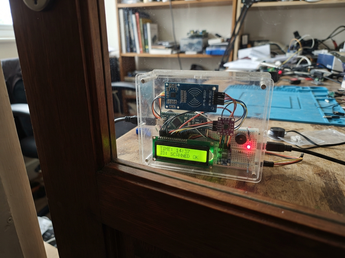
This smart NFC attendance terminal uses an ESP32 microcontroller to read RFID cards and report attendance data to a central server. The system combines an MFRC522 card reader, 16x2 LCD display, status LEDs, and buzzer to create a complete check-in station that can be deployed at school gates or entry points.
This guide provides a complete wiring diagram, parts list, and step-by-step assembly instructions. The included firmware handles WiFi connectivity, card scanning with debouncing, real-time feedback via the LCD and indicator lights, and HTTP communication with a backend API. Customize the network credentials and server endpoint to integrate with your attendance tracking system.
Wiring diagram

Gather all the parts
Assemble it in 7 steps
1. Place the ESP32 and make a shared ground
Place the ESP32 DevKit v1 across the breadboard centre gap. Run one black jumper from an ESP32 GND pin to the breadboard ground rail; every module in this build connects to that same ground rail so their signals have the same reference.
- Keep the USB connector facing outward so you can plug it in after the wiring is complete.
2. Wire the card reader
Connect rfid_reader VCC to ESP32 3V3 (power), GND to the shared GND rail (ground), SCK to GPIO18 (clock), MISO to GPIO19 (data back to the ESP32), MOSI to GPIO23 (data to the reader), SDA/SS to GPIO5 (reader select), and RST to GPIO4 (reset).
- Use only 3.3V for the MFRC522 VCC pin — connecting its VCC to 5V can damage the reader.
- Keep the reader's SDA/SS wire connected to GPIO5 and do not let it be held low while the ESP32 is starting, or the ESP32 may fail to boot.
3. Connect the LCD through the protection board
Connect i2c_level_shifter LV to ESP32 3V3 (power), HV to ESP32 5V/VIN (power), and GND to the shared GND rail (ground). Connect LV1 to GPIO21 (LCD data) and LV2 to GPIO22 (LCD clock). Connect HV1 to lcd_1602 SDA (data) and HV2 to lcd_1602 SCL (clock). Finally connect lcd_1602 VCC to ESP32 5V/VIN (power) and lcd_1602 GND to the shared GND rail (ground).
- The I2C level-shifter has a low-voltage side marked LV and a high-voltage side marked HV; match these labels carefully.
- Turn the small contrast screw on the LCD slowly if the backlight comes on but letters are not visible.
- Do not connect the LCD's 5V SDA or SCL wires directly to GPIO21 or GPIO22 — 5V on these ESP32 pins can damage the board.
4. Wire the buzzer
Connect buzzer SIGNAL or + to GPIO25 (sound signal) and buzzer GND or - to the shared GND rail (ground).
- This design assumes a 3.3V active buzzer. Do not connect a 5V-only buzzer directly to GPIO25 because that can overload the ESP32 pin.
5. Wire the green success light
Connect green_led_resistor P1 to GPIO26 (signal), connect its other lead P2 to the long leg of green_led (positive side), then connect the green LED's short leg, or flat-side leg, to the shared GND rail (ground).
- Leave the 220 Ω resistor in series with the LED — connecting an LED directly to GPIO26 can damage the LED or the ESP32 pin.
6. Wire the red rejection light
Connect red_led_resistor P1 to GPIO32 (signal), connect its other lead P2 to the long leg of red_led (positive side), then connect the red LED's short leg, or flat-side leg, to the shared GND rail (ground).
- Leave the 220 Ω resistor in series with the LED — connecting an LED directly to GPIO32 can damage the LED or the ESP32 pin.
7. Check power before plugging in
Check that all ground wires meet at the same ground rail, the MFRC522 is on 3.3V, and only the LCD plus the high-voltage side of i2c_level_shifter use 5V. Then connect the ESP32 to USB power.
- The LCD should light up and initially show that it is connecting to Wi-Fi.
Review all connections
1. Connections between "rfid_reader" and "ESP32"
2. Connections between "i2c_level_shifter" and "ESP32"
3. Connections between "lcd_1602" and "ESP32"
4. Connections between "buzzer" and "ESP32"
5. Connections between "green_led_resistor" and "ESP32"
6. Connections between "green_led" and "ESP32"
7. Connections between "red_led_resistor" and "ESP32"
8. Connections between "red_led" and "ESP32"
Deploy the firmware
#include <Arduino.h>
#include <WiFi.h>
#include <HTTPClient.h>
#include <SPI.h>
#include <MFRC522.h>
#include <Wire.h>
#include <LiquidCrystal_I2C.h>
#include <ArduinoJson.h>

// Replace these three values with the school network and central API details.

// Forward declarations
void printLine(uint8_t row, const String &text);
void setIndicators(bool green, bool red);
void beep(uint8_t times);
void showReady();
void showResult(const String &line1, const String &line2, bool accepted);
String cardUidHex();
void startWifiConnection();
void maintainWifi();
void sendCardEvent(const String &uid);

const char *WIFI_SSID = "YOUR_SCHOOL_WIFI";
const char *WIFI_PASSWORD = "YOUR_WIFI_PASSWORD";
const char *API_URL = "http://YOUR_SERVER_OR_APPS_SCRIPT_ENDPOINT";
const char *TERMINAL_ID = "GATE_01";

constexpr uint8_t RFID_SS_PIN = 5;
constexpr uint8_t RFID_RST_PIN = 4;
constexpr uint8_t RFID_SCK_PIN = 18;
constexpr uint8_t RFID_MISO_PIN = 19;
constexpr uint8_t RFID_MOSI_PIN = 23;
constexpr uint8_t I2C_SDA_PIN = 21;
constexpr uint8_t I2C_SCL_PIN = 22;
constexpr uint8_t BUZZER_PIN = 25;
constexpr uint8_t GREEN_LED_PIN = 26;
constexpr uint8_t RED_LED_PIN = 32;

constexpr unsigned long SCAN_DEBOUNCE_MS = 2000;
constexpr unsigned long RESULT_SCREEN_MS = 3000;
constexpr unsigned long WIFI_RETRY_MS = 10000;

MFRC522 rfid(RFID_SS_PIN, RFID_RST_PIN);
LiquidCrystal_I2C lcd(0x27, 16, 2);

unsigned long lastScanMs = 0;
unsigned long resultUntilMs = 0;
unsigned long lastWifiAttemptMs = 0;
bool showingResult = false;

void printLine(uint8_t row, const String &text) {
  String line = text;
  if (line.length() > 16) line = line.substring(0, 16);
  while (line.length() < 16) line += ' ';
  lcd.setCursor(0, row);
  lcd.print(line);
}

void setIndicators(bool green, bool red) {
  digitalWrite(GREEN_LED_PIN, green ? HIGH : LOW);
  digitalWrite(RED_LED_PIN, red ? HIGH : LOW);
}

void beep(uint8_t times) {
  for (uint8_t i = 0; i < times; i++) {
    digitalWrite(BUZZER_PIN, HIGH);
    delay(120);
    digitalWrite(BUZZER_PIN, LOW);
    if (i + 1 < times) delay(120);
  }
}

void showReady() {
  showingResult = false;
  setIndicators(false, false);
  printLine(0, "School System");
  if (WiFi.status() == WL_CONNECTED) {
    printLine(1, "Ready: Tap Card");
  } else {
    printLine(1, "WiFi reconnecting");
  }
}

void showResult(const String &line1, const String &line2, bool accepted) {
  printLine(0, line1);
  printLine(1, line2);
  setIndicators(accepted, !accepted);
  beep(accepted ? 1 : 2);
  showingResult = true;
  resultUntilMs = millis() + RESULT_SCREEN_MS;
}

String cardUidHex() {
  String uid;
  for (byte i = 0; i < rfid.uid.size; i++) {
    if (rfid.uid.uidByte[i] < 0x10) uid += '0';
    uid += String(rfid.uid.uidByte[i], HEX);
  }
  uid.toUpperCase();
  return uid;
}

void startWifiConnection() {
  if (strlen(WIFI_SSID) == 0 || String(WIFI_SSID).startsWith("YOUR_")) return;
  WiFi.mode(WIFI_STA);
  WiFi.begin(WIFI_SSID, WIFI_PASSWORD);
  lastWifiAttemptMs = millis();
}

void maintainWifi() {
  if (WiFi.status() == WL_CONNECTED) return;
  if (millis() - lastWifiAttemptMs >= WIFI_RETRY_MS) {
    WiFi.disconnect();
    startWifiConnection();
  }
}

void sendCardEvent(const String &uid) {
  if (WiFi.status() != WL_CONNECTED) {
    showResult("Network Offline", "Try again soon", false);
    return;
  }
  if (String(API_URL).startsWith("http://YOUR_")) {
    showResult("API not set", "Set API_URL", false);
    return;
  }

  JsonDocument request;
  request["uid"] = uid;
  request["terminal_id"] = TERMINAL_ID;
  String payload;
  serializeJson(request, payload);

  HTTPClient http;
  http.setTimeout(8000);
  http.begin(API_URL);
  http.addHeader("Content-Type", "application/json");
  const int httpCode = http.POST(payload);
  const String response = (httpCode > 0) ? http.getString() : "";
  http.end();

  if (httpCode != HTTP_CODE_OK) {
    showResult("Server Error", httpCode > 0 ? "HTTP " + String(httpCode) : "Request failed", false);
    return;
  }

  JsonDocument reply;
  DeserializationError error = deserializeJson(reply, response);
  if (error) {
    showResult("Server Error", "Bad JSON reply", false);
    return;
  }

  const String status = reply["status"] | "error";
  const String name = reply["name"] | "";
  const String message = reply["message"] | "";
  const bool accepted = (status == "success");

  if (!accepted) {
    showResult("Access Denied", message.length() ? message : "Request rejected", false);
    return;
  }

  String top = name.length() ? name + " (OK)" : "Accepted";
  String bottom = message;
  if (!reply["balance"].isNull()) {
    bottom = "Bal: " + String(reply["balance"].as<float>(), 0) + " THB";
  }
  if (!bottom.length()) bottom = "Checked In";
  showResult(top, bottom, true);
}

void setup() {
  pinMode(BUZZER_PIN, OUTPUT);
  pinMode(GREEN_LED_PIN, OUTPUT);
  pinMode(RED_LED_PIN, OUTPUT);
  setIndicators(false, false);
  digitalWrite(BUZZER_PIN, LOW);

  Wire.begin(I2C_SDA_PIN, I2C_SCL_PIN);
  lcd.init();
  lcd.backlight();
  printLine(0, "School System");
  printLine(1, "Connecting WiFi");

  SPI.begin(RFID_SCK_PIN, RFID_MISO_PIN, RFID_MOSI_PIN, RFID_SS_PIN);
  rfid.PCD_Init();
  startWifiConnection();
}

void loop() {
  maintainWifi();

  if (showingResult && millis() >= resultUntilMs) showReady();
  if (showingResult) return;

  if (!rfid.PICC_IsNewCardPresent() || !rfid.PICC_ReadCardSerial()) return;
  if (millis() - lastScanMs < SCAN_DEBOUNCE_MS) {
    rfid.PICC_HaltA();
    rfid.PCD_StopCrypto1();
    return;
  }

  lastScanMs = millis();
  const String uid = cardUidHex();
  rfid.PICC_HaltA();
  rfid.PCD_StopCrypto1();
  printLine(0, "Card detected");
  printLine(1, "Contacting server");
  sendCardEvent(uid);
}
Remix this project
Make it yours in one click
Open a full copy of this project in your own Schematik workspace — diagram, code, parts, and assembly steps included. Swap the sensor, add features, or redesign the whole thing with AI. The author's original stays untouched.