Community project
Use Both Boards Pic32cm Reads Touch Controls Sen
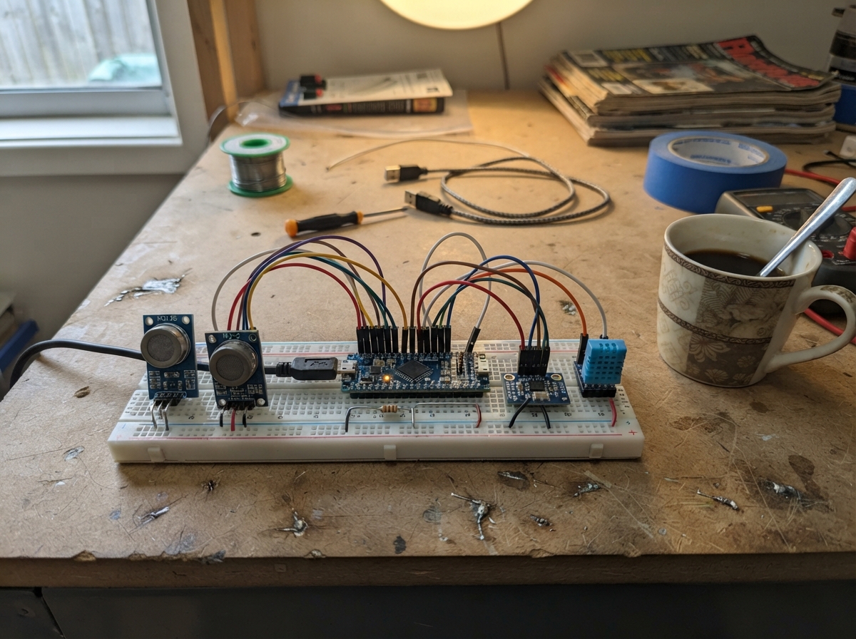
This project combines an ESP32 microcontroller with a PIC32CM LS00 touch evaluation board to build a multi-sensor air quality monitor. The system reads temperature and humidity from a DHT11 sensor, measures gas concentrations using MQ135 and MQ-2 sensors connected through an ADS1115 analog-to-digital converter, and accepts user input via capacitive touch controls on the dedicated touch board. Both microcontrollers communicate over serial, sharing a common ground and power rail on a breadboard.
The guide provides a complete wiring diagram showing how to safely connect the low-cost gas sensors with voltage dividers, the I2C connections for the ADC module, and the serial link between the two boards. Readers will receive the full Arduino firmware with WiFi access point setup, real-time sensor sampling, baseline calibration for gas sensors, and a web dashboard to monitor all readings. Assembly steps cover breadboard layout, safe voltage divider construction, and sensor initialization with a warmup period.
Wiring diagram

Gather all the parts
Assemble it in 6 steps
1. Place the two boards and make a shared ground
Put the ESP32 DevKit, the PIC32CM touch board, ADS1115 module, MQ-135 module, MQ-2 module, and DHT11 module on or beside the breadboard. Join an ESP32 GND pin to the breadboard ground rail, then connect both MQ GND pins, ADS1115 GND, DHT11 GND, and PIC32CM GND to that same rail so every board has the same electrical reference.
- Use black jumpers for the shared ground rail so it is easy to trace later.
- Do not connect a sensor output before the grounds are shared; without the common ground the readings can be wrong or unstable.
2. Power the low-cost sensor modules
Connect each MQ module VCC pin to the ESP32 5V/VIN rail and each MQ module GND pin to the ground rail. Connect ADS1115 VDD to ESP32 3V3, ADS1115 GND to ground, DHT11 VCC to ESP32 3V3, and DHT11 GND to ground. The MQ modules need 5 V for their small heaters; the ADS1115 and DHT11 use the safer 3.3 V rail.
- Use red wires for 5 V, orange wires for 3.3 V, and black wires for ground.
- Do not connect either MQ module's A0/AO pin directly to an ESP32 pin or the ADS1115 input — it can rise to 5 V and damage 3.3 V electronics.
3. Build the two safe voltage-divider connections
For MQ-135, connect A0 to one end of its 20 kΩ resistor. Connect the other end of that 20 kΩ resistor to ADS1115 AIN0 and also to one end of its 10 kΩ resistor. Connect the free end of the 10 kΩ resistor to GND. Repeat the same pattern for MQ-2: AO → its 20 kΩ resistor → ADS1115 AIN1, with its 10 kΩ resistor from that AIN1 junction to GND. These two resistor pairs reduce the modules' 5 V analogue signals to a safe voltage.
- Keep each pair of resistor legs in the same breadboard row at the ADC junction: MQ-135 junction goes to AIN0 and MQ-2 junction goes to AIN1.
- Swapping a resistor connection can leave a 5 V signal at the ADC input. Check that each 10 kΩ resistor ends at GND before powering the circuit.
4. Wire the digital sensors
Connect ADS1115 SDA to ESP32 GPIO21 and ADS1115 SCL to ESP32 GPIO22. Connect DHT11 DATA to ESP32 GPIO4. These wires carry the readings to the ESP32; the ADS1115 is the small converter that reads the two analogue gas-module outputs.
- Keep the SDA and SCL wires short and use different colors so they are not mixed up.
- Make sure VDD and GND are not swapped on the ADS1115 or DHT11 — swapped power can damage a module.
5. Connect the touch board
Connect PIC32CM 3V3 to the ESP32 3V3 rail and PIC32CM GND to the shared ground rail. Connect PIC32CM PA16 / SERCOM3 TX to ESP32 GPIO16, and PIC32CM PA17 / SERCOM3 RX to ESP32 GPIO17. The touch-board firmware should send the text MODE followed by a new line for a touch action to change the dashboard mode.
- Cross-check the labels on the board itself before connecting UART wires; TX sends and RX receives.
- Both boards must use 3.3 V logic. Do not attach either UART pin to the MQ modules' 5 V output.
6. Run the monitor and let it settle
Plug the ESP32 into USB power. Keep both MQ modules in clean room air for at least one minute before judging the dashboard trend, because their heated sensing elements must settle. Connect a phone or computer to the Air-Monitor Wi-Fi network and open 192.168.4.1 to see readings every five seconds.
- Keep the modules away from the ESP32's warm voltage regulator and away from direct breath while making a baseline.
- MQ modules get warm during normal operation. Do not cover them, touch the metal sensor cap while hot, or use them as safety equipment for smoke, gas leaks, or hazardous air.
Review all connections
1. Connections between "pic32cm_touch" and "ESP32"
2. Connections between "mq135_1" and "ESP32"
3. Connections between "mq2_1" and "ESP32"
4. Connections between "ads1115_1" and "ESP32"
5. Connections between "dht11_1" and "ESP32"
6. Connections between "resistor_20k_1" and "ESP32"
7. Connections between "resistor_10k_1" and "ESP32"
8. Connections between "resistor_20k_2" and "ESP32"
9. Connections between "resistor_10k_2" and "ESP32"
Deploy the firmware
#include <Arduino.h>
#include <WiFi.h>
#include <WebServer.h>
#include <Wire.h>
#include <Adafruit_ADS1X15.h>
#include <DHT.h>


// Hoisted type definitions
struct Readings {
  float temperature = NAN;
  float humidity = NAN;
  float mq135Volts = NAN;
  float mq2Volts = NAN;
  float mq135Baseline = NAN;
  float mq2Baseline = NAN;
  bool unusualAir = false;
  uint32_t updatedAt = 0;
} data;


// Forward declarations
String numberOrNull(float value, uint8_t decimals);
float readAveragedVolts(uint8_t channel);
void updateBaseline(float &baseline, float reading);
void sampleSensors();
void sendJson();
void readTouchCommands();

constexpr int I2C_SDA = 21;
constexpr int I2C_SCL = 22;
constexpr int DHT_PIN = 4;
constexpr int TOUCH_RX_PIN = 16;
constexpr int TOUCH_TX_PIN = 17;
constexpr uint32_t SENSOR_INTERVAL_MS = 5000;
constexpr uint32_t MQ_WARMUP_MS = 60000;
constexpr uint8_t ADC_SAMPLES = 8;

const char *AP_NAME = "Air-Monitor";
const char *AP_PASSWORD = "airmonitor2026";


WebServer server(80);
Adafruit_ADS1115 ads;
DHT dht(DHT_PIN, DHT11);

bool compactMode = false;
bool adsReady = false;
uint32_t lastSample = 0;
String touchLine;

const char DASHBOARD[] PROGMEM = R"HTML(
<!doctype html><html><head><meta name="viewport" content="width=device-width,initial-scale=1">
<style>body{font-family:Arial;margin:20px;background:#10221c;color:#edf7f1}h1{color:#79e0a6}.grid{display:grid;grid-template-columns:repeat(auto-fit,minmax(150px,1fr));gap:12px}.card{background:#1d3a2f;padding:14px;border-radius:12px}.v{font-size:1.7em;font-weight:bold;color:#b9ffd3}.small{color:#b8c9c0}.warn{color:#ffce6b;font-weight:bold}button{padding:12px;border:0;border-radius:8px;background:#79e0a6;color:#10221c;font-weight:bold}</style>
</head><body><h1>College Air Monitor</h1><p id="state">Loading…</p><div class="grid">
<div class="card">MQ-135 air trend<div class="v" id="mq135">--</div><div class="small">relative level, not ppm</div></div>
<div class="card">MQ-2 smoke / gas trend<div class="v" id="mq2">--</div><div class="small">relative level, not ppm</div></div>
<div class="card">Temperature<div class="v" id="temp">--</div><div class="small">°C</div></div>
<div class="card">Humidity<div class="v" id="hum">--</div><div class="small">%</div></div></div>
<p id="alert" class="warn"></p><p><button onclick="fetch('/touch').then(load)">Change display mode</button></p>
<script>function n(x,d=2){return x===null?'--':Number(x).toFixed(d)}function load(){fetch('/data').then(r=>r.json()).then(x=>{mq135.textContent=n(x.mq135,2);mq2.textContent=n(x.mq2,2);temp.textContent=n(x.temperature,1);hum.textContent=n(x.humidity,1);alert.textContent=x.unusual?'Unusual change from the warmed-up air baseline.':'Air trend is near its warmed-up baseline.';state.textContent='Updated '+new Date(x.updatedAt).toLocaleTimeString()+' · '+x.mode+(x.warming?' · warming up':'');});}load();setInterval(load,5000);</script></body></html>
)HTML";

String numberOrNull(float value, uint8_t decimals = 2) {
  return isnan(value) ? "null" : String(value, decimals);
}

float readAveragedVolts(uint8_t channel) {
  int32_t total = 0;
  for (uint8_t i = 0; i < ADC_SAMPLES; ++i) {
    total += ads.readADC_SingleEnded(channel);
    delay(2);
  }
  // ADS1115 GAIN_ONE: 4.096 V full-scale, 0.125 mV per count.
  return (total / static_cast<float>(ADC_SAMPLES)) * 0.000125F;
}

void updateBaseline(float &baseline, float reading) {
  if (isnan(baseline)) baseline = reading;
  else baseline = baseline * 0.95F + reading * 0.05F;
}

void sampleSensors() {
  float newTemperature = dht.readTemperature();
  float newHumidity = dht.readHumidity();
  if (!isnan(newTemperature)) data.temperature = newTemperature;
  if (!isnan(newHumidity)) data.humidity = newHumidity;

  if (adsReady) {
    data.mq135Volts = readAveragedVolts(0);
    data.mq2Volts = readAveragedVolts(1);
    if (millis() >= MQ_WARMUP_MS) {
      updateBaseline(data.mq135Baseline, data.mq135Volts);
      updateBaseline(data.mq2Baseline, data.mq2Volts);
      float mq135Change = fabsf(data.mq135Volts - data.mq135Baseline);
      float mq2Change = fabsf(data.mq2Volts - data.mq2Baseline);
      data.unusualAir = mq135Change > 0.12F || mq2Change > 0.12F;
    }
  }
  data.updatedAt = millis();
}

void sendJson() {
  bool warming = millis() < MQ_WARMUP_MS;
  String json = "{";
  json += "\"mq135\":" + numberOrNull(data.mq135Volts);
  json += ",\"mq2\":" + numberOrNull(data.mq2Volts);
  json += ",\"temperature\":" + numberOrNull(data.temperature);
  json += ",\"humidity\":" + numberOrNull(data.humidity);
  json += ",\"unusual\":" + String(data.unusualAir ? "true" : "false");
  json += ",\"warming\":" + String(warming ? "true" : "false");
  json += ",\"updatedAt\":" + String(data.updatedAt);
  json += ",\"mode\":\"" + String(compactMode ? "compact" : "full") + "\"}";
  server.send(200, "application/json", json);
}

void readTouchCommands() {
  while (Serial2.available()) {
    char c = static_cast<char>(Serial2.read());
    if (c == '\n' || c == '\r') {
      touchLine.trim();
      if (touchLine == "MODE" || touchLine == "TOUCH") compactMode = !compactMode;
      touchLine = "";
    } else if (touchLine.length() < 24) touchLine += c;
  }
}

void setup() {
  Serial.begin(115200);
  Serial2.begin(115200, SERIAL_8N1, TOUCH_RX_PIN, TOUCH_TX_PIN);
  Wire.begin(I2C_SDA, I2C_SCL);
  dht.begin();
  adsReady = ads.begin(0x48, &Wire);
  if (adsReady) ads.setGain(GAIN_ONE);

  WiFi.mode(WIFI_AP);
  WiFi.softAP(AP_NAME, AP_PASSWORD);
  server.on("/", []() { server.send_P(200, "text/html", DASHBOARD); });
  server.on("/data", sendJson);
  server.on("/touch", []() { compactMode = !compactMode; server.send(204); });
  server.begin();
}

void loop() {
  server.handleClient();
  readTouchCommands();
  if (millis() - lastSample >= SENSOR_INTERVAL_MS) {
    lastSample = millis();
    sampleSensors();
  }
}
Remix this project
Make it yours in one click
Open a full copy of this project in your own Schematik workspace — diagram, code, parts, and assembly steps included. Swap the sensor, add features, or redesign the whole thing with AI. The author's original stays untouched.