Community project
Smart Soil Watering System
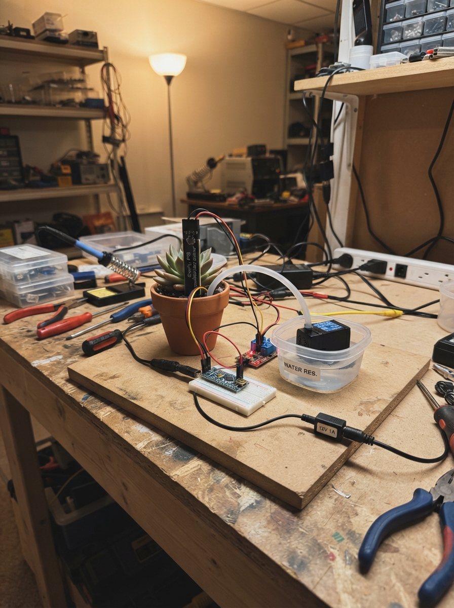
This smart watering system automatically waters plants when soil moisture drops below a set threshold, using an ESP32 microcontroller to monitor a capacitive soil sensor and control a 12V submersible pump via a relay. The system includes built-in safeguards like a 30-minute lockout period between waterings and a requirement for multiple dry readings before activating the pump, preventing overwatering and pump burnout.
The guide provides a complete wiring diagram showing how to safely isolate the high-voltage pump circuit from the low-voltage sensor and control electronics, a full parts list with sourcing information, calibration instructions for the soil moisture threshold, and step-by-step assembly directions. Builders will also receive the complete Arduino firmware with configurable timing parameters and serial debugging output.
Wiring diagram

Gather all the parts
Assemble it in 5 steps
1. Keep the electronics away from water
Put the NodeMCU board and relay module in a dry plastic box above the soil and reservoir. Feed the sensor cable and pump wires out through separate holes so water cannot drip onto the boards.
- Make a drip loop in each cable: let the cable dip below the box hole before it rises into the box, so water drips off the lowest point.
- Water touching the NodeMCU, relay board, or bare wire joints can cause a short circuit and damage the parts.
2. Wire the soil sensor
Connect the soil sensor red VCC wire to NodeMCU 3V3 (power), its black GND wire to NodeMCU GND (ground), and its yellow AOUT wire to NodeMCU A0 (signal). Push only the sensing end into the soil; keep the cable connection above wet soil.
- Place the sensor near the plant roots, not directly under the water outlet, so it measures the soil rather than a freshly wet puddle.
- Do not connect the sensor VCC wire to the 12 V adapter — 12 V can damage the sensor and the NodeMCU.
3. Wire the relay control side
Connect relay VCC to NodeMCU 3V3 (power), relay GND to NodeMCU GND (ground), and relay IN to NodeMCU D1 / GPIO5 (signal). Use a relay module marked as accepting a 3.3 V control signal.
- The relay board may click briefly when the NodeMCU starts; this project starts with the pump command off.
- Do not use a bare relay coil. Use the ready-made relay module because it includes the parts needed to protect the NodeMCU control pin.
4. Wire the 12 V pump path
With the 12 V adapter unplugged, connect adapter +12V to relay COM (switched power source), relay NO to pump PUMP+ (switched power), and adapter GND to pump PUMP- (return). NO means the pump remains off until the relay is commanded on.
- If the pump has red and black leads, red normally goes to PUMP+ and black normally goes to PUMP-. Use screw terminals or insulated connectors, not twisted bare wires.
- Never connect the 12 V adapter to NodeMCU 3V3, A0, D1, or USB; 12 V on those connections can permanently damage the board.
5. Position the water parts
Put the pump fully in its water reservoir and run its outlet tube to the plant. Keep the water level above the pump intake before turning it on so the pump does not run dry.
- Secure the tube so it points into the pot and cannot spray the electronics.
- Running a submersible pump without water can overheat and damage it.
Review all connections
1. Connections between "soil_sensor" and "ESP32"
2. Connections between "pump_relay" and "ESP32"
3. Connections between "power_adapter" and "ESP32"
Deploy the firmware
#include <Arduino.h>


// Forward declarations
void setPump(bool on);

constexpr uint8_t SOIL_SENSOR_PIN = A0;
constexpr uint8_t RELAY_PIN = 5;  // NodeMCU D1

// Calibrate these two values after installation. Higher values generally mean drier soil.
constexpr int DRY_THRESHOLD = 650;
constexpr unsigned long SAMPLE_INTERVAL_MS = 1000UL;
constexpr unsigned long WATERING_TIME_MS = 10000UL;
constexpr unsigned long LOCKOUT_TIME_MS = 1800000UL;  // 30 minutes
constexpr uint8_t DRY_SAMPLES_REQUIRED = 3;

bool pumpRunning = false;
uint8_t drySamples = 0;
unsigned long lastSampleAt = 0;
unsigned long pumpStartedAt = 0;
unsigned long nextWateringAllowedAt = 0;

void setPump(bool on) {
  // The selected relay module is active-low: LOW closes the relay.
  digitalWrite(RELAY_PIN, on ? LOW : HIGH);
  pumpRunning = on;
  Serial.println(on ? F("Pump ON") : F("Pump OFF"));
}

void setup() {
  Serial.begin(115200);
  pinMode(RELAY_PIN, OUTPUT);
  setPump(false);  // Keep water off during startup.
  Serial.println(F("Smart sprinkler ready"));
}

void loop() {
  const unsigned long now = millis();

  if (pumpRunning && now - pumpStartedAt >= WATERING_TIME_MS) {
    setPump(false);
    nextWateringAllowedAt = now + LOCKOUT_TIME_MS;
    drySamples = 0;
    Serial.println(F("Watering complete; waiting 30 minutes"));
  }

  if (now - lastSampleAt < SAMPLE_INTERVAL_MS) {
    return;
  }
  lastSampleAt = now;

  const int moistureReading = analogRead(SOIL_SENSOR_PIN);
  const bool soilIsDry = moistureReading >= DRY_THRESHOLD;
  Serial.print(F("Soil reading: "));
  Serial.print(moistureReading);
  Serial.print(F(" - "));
  Serial.println(soilIsDry ? F("dry") : F("wet"));

  if (!soilIsDry) {
    drySamples = 0;
    return;
  }

  if (drySamples < DRY_SAMPLES_REQUIRED) {
    ++drySamples;
  }

  if (!pumpRunning && now >= nextWateringAllowedAt && drySamples >= DRY_SAMPLES_REQUIRED) {
    pumpStartedAt = now;
    setPump(true);
  }
}
Remix this project
Make it yours in one click
Open a full copy of this project in your own Schematik workspace — diagram, code, parts, and assembly steps included. Swap the sensor, add features, or redesign the whole thing with AI. The author's original stays untouched.
Related projects

Create A Complete Electrical Schematic Esp32 Sma
ESP32 · September 17, 2026Ayansh Agrawal
ESP32 Kare Ekran Projeleri
ESP32 · September 16, 2026Seref Ai
Component Qty --------------------------- ------
ESP32 · September 16, 2026Yathartha Chakrawal