Community project
Smart Thermal Printing Calculator
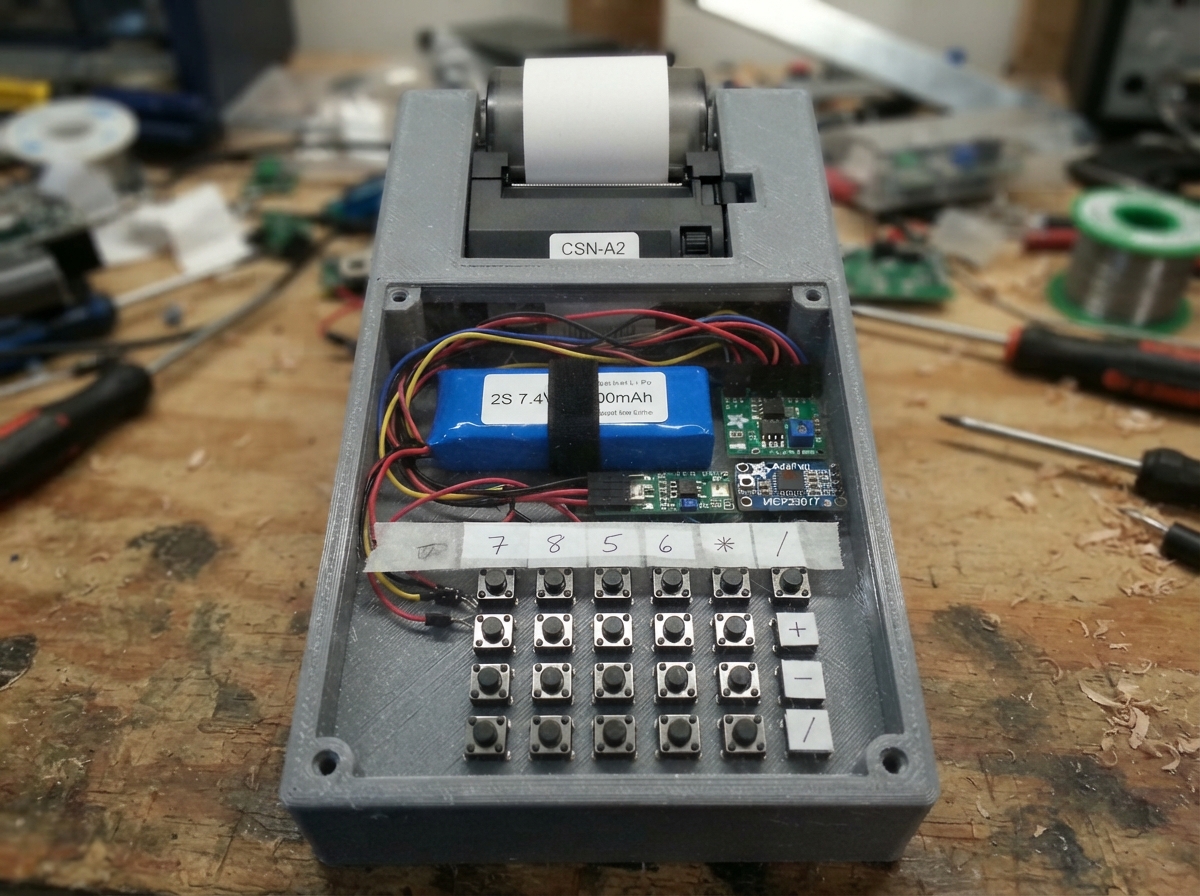
This project builds a portable calculator with a thermal printer and a large color touchscreen display, powered by an ESP32 microcontroller. The device combines a 35-key calculator keypad, a 4.58-inch RGB IPS display, and a CSN-A2 thermal printer to create a compact computing tool that can print receipts and calculations on demand.
The guide provides a complete wiring diagram, detailed parts list, and step-by-step assembly instructions to integrate the power management system (including Li-Po battery, BMS protection, fuel gauge, and USB-C charging), dual voltage rails for the printer and logic circuits, and all peripheral connections. Firmware code is included to handle the display rendering, keypad scanning, printer communication, and battery monitoring through LVGL graphics and the MCP23017 I/O expander.
Wiring diagram

Gather all the parts
Assemble it in 6 steps
1. Install the named power modules
Mount the Adafruit HUSB238 USB-C PD Dummy board (usb_c_pd_sink), the selected 2S USB-C power-path charger board (charger_2s_powerpath), and the MP1584EN mini buck module (buck_5v) close to the case power opening. Connect HUSB238 `+` to the charger `VBUS` terminal (USB-C input power) and HUSB238 `GND` to charger `GND` (ground). Set the HUSB238 hardware selection for the voltage accepted by the exact charger board; this design presently uses 9 V.
- The exact label to look for on the small buck board is `MP1584EN`.
- The charger board must explicitly provide a battery-free `SYS`, `LOAD`, or `OUT` terminal rated for at least 5 A.
- The charger board has not been assigned a model number because its manufacturer and terminal layout were not supplied; buy only one matching the stated SYS/LOAD requirement.
- Do not connect the wall socket to any internal wire. Only connect a certified USB-C PD adapter to the HUSB238 USB-C socket.
- Do not connect the calculator load to `VBUS`; `VBUS` is the charger input, while `SYS` or `LOAD` powers the calculator.
2. Create the 9 V printer rail and 5 V logic rail
Connect the charger module `SYS` / `LOAD` output to the CSN-A2 printer `VH` terminal (printer power) and the MP1584EN `VIN` terminal (power). Connect charger `GND`, printer `GND`, and MP1584EN `GND` together (ground). With only the power modules connected, adjust the MP1584EN trimmer until `VOUT` measures exactly 5.0 V relative to GND. Connect its `VOUT` to ESP32-S3 `5V/VIN`, the ST7701S display `VCC`, and the 74LVC2T45 `VCCB` (5 V power).
- Use short 18–20 AWG paired wires between SYS/LOAD and the CSN-A2 printer because the print head takes brief high-current pulses.
- The small module used here is specifically the MP1584EN, replacing the larger LM2596 module.
- Make sure the MP1584EN output is 5.0 V before connecting the ESP32-S3. A higher setting can permanently damage the board and display.
- Make sure every ground named here is connected together; a missing ground makes signals unreliable.
3. Connect the exact logic parts
Power the MCP23017 keypad expander and MAX17049 fuel-gauge board from ESP32-S3 `3V3` (power) and common ground (ground). Connect each board's `SDA` to GPIO8 (data) and `SCL` to GPIO9 (clock). Connect the 74LVC2T45 level translator: `VCCA` and `DIR1` to 3V3 (power), `VCCB` to 5 V (power), `GND` and `DIR2` to GND (ground), `A1` to GPIO5 (printer data out), `B1` to CSN-A2 `RX` (printer data), CSN-A2 `TX` to `B2` (printer data), and `A2` to GPIO4 (printer data in).
- Model labels in this section are MAX17049, MCP23017, and 74LVC2T45.
- The 74LVC2T45 prevents the CSN-A2 printer's possible 5 V TX signal from reaching the ESP32-S3 directly.
- Use a MAX17049 breakout with 3.3 V-safe I2C pins. A board that drives SDA or SCL at 5 V can damage the ESP32-S3.
- Do not omit the 74LVC2T45 between the printer and ESP32-S3.
4. Wire the display and keypad
Connect the ST7701S 4.58-inch 320×960 RGB display setup pins: `SPI_CS` to GPIO41 (data), `SPI_SCK` to GPIO42 (clock), and `SPI_MOSI` to GPIO47 (data). Connect its timing pins `DE` to GPIO38 (screen-area signal), `VSYNC` to GPIO40 (frame signal), `HSYNC` to GPIO39 (line signal), and `PCLK` to GPIO21 (pixel timing). Connect RGB data pins exactly as shown in the wiring diagram. Connect the 35 tactile switches as a 6-by-7 matrix to MCP23017 `GPA0–GPA5` for rows and `GPB0–GPB6` for columns, with one 1N4148 diode in series with every switch; put each diode's striped end toward its row wire.
- The display driver is ST7701S; obtain its panel-specific initialization timing from the seller because separate 4.58-inch ST7701S panels can have different timing values.
- The diode marking band is the striped end.
- Make sure the ST7701S module accepts 3.3 V RGB and setup signals. Do not connect a 5 V logic-output display module directly to the ESP32-S3.
- Keep the display ribbon and RGB wires away from the printer power wires to reduce picture noise.
5. Leave the future battery parts disconnected
For the present USB-C-only build, leave the 2 × 606090 2S pack, HW-391 2S BMS board, and 5 A blade fuse holder disconnected. Later, connect battery `PACK+` through the 5 A fuse to HW-391 `B+` (battery positive), battery `MID` to HW-391 `B1` (middle-cell sense), and battery `PACK−` to HW-391 `B−` (battery negative). Connect HW-391 `P+` to charger `VBAT` (battery power) and HW-391 `P−` to common ground (ground). Connect MAX17049 `CELL` to HW-391 `P+` (battery measurement).
- HW-391 is the protection-board label supplied by you; verify its printed terminals before attaching cells.
- The MAX17049 cannot report a useful battery value while the battery is absent.
- Insulate every unused future battery wire so it cannot touch another wire or the metal enclosure.
- Never reverse a Li-Po connection. A reversed or shorted pack can overheat or catch fire.
6. Check voltages and power the calculator
Check for loose wire strands. Plug a USB-C PD adapter into the Adafruit HUSB238 board. Measure about 9 V at the charger's `SYS` / `LOAD` terminal and exactly 5.0 V at MP1584EN `VOUT`. Only then connect the ESP32-S3 through its USB programming connector, load paper into the CSN-A2 printer, and press Deploy in Schematik.
- If printing causes resets, first inspect the SYS-to-CSN-A2 wire thickness and confirm that the adapter truly supplies the requested PD voltage.
- The model labels in the final power path are HUSB238 → selected 2S power-path charger → MP1584EN.
- Unplug immediately if a connector, wire, printer, or module becomes hot.
- Do not install batteries until the battery wiring has been checked against the printing on the actual HW-391 and charger boards.
Review all connections
1. Connections between "battery_pack_2s" and "ESP32"
2. Connections between "battery_fuse" and "ESP32"
3. Connections between "printer_58mm" and "ESP32"
4. Connections between "fuel_gauge" and "ESP32"
5. Connections between "keypad_expander" and "ESP32"
6. Connections between "keypad_6x7" and "ESP32"
7. Connections between "key_diodes" and "ESP32"
8. Connections between "display_st7701s" and "ESP32"
9. Connections between "uart_level_shifter" and "ESP32"
10. Connections between "charger_2s_powerpath" and "ESP32"
11. Connections between "bms_2s" and "ESP32"
12. Connections between "usb_c_pd_sink" and "ESP32"
13. Connections between "buck_5v" and "ESP32"
Deploy the firmware
#include <Arduino.h>
#include <Wire.h>
#include <WiFi.h>
#include <NimBLEDevice.h>
#include <Adafruit_MCP23X17.h>
#include <Adafruit_Thermal.h>
#include <Arduino_GFX_Library.h>
#include <lvgl.h>

#define LCD_B1 17
#define LCD_B2 18
#define LCD_B3 19
#define LCD_B4 20
#define LCD_G1 11
#define LCD_G2 12
#define LCD_G3 13
#define LCD_G4 14
#define LCD_G5 15
#define LCD_R1 2
#define LCD_R2 3
#define LCD_R3 6
#define LCD_R4 7
#define LCD_SPI_SCK 42
#define LCD_SPI_MOSI 47


// Forward declarations
void flushDisplay(lv_disp_drv_t *disp, const lv_area_t *area, lv_color_t *colorMap);
void initDisplay();
void initKeypad();
void printMockReceipt();
void onKeyPressed(uint8_t row, uint8_t col);
void scanKeypad();
void readFuelGauge();
void initConnectivityStubs();

constexpr int I2C_SDA = 8;
constexpr int I2C_SCL = 9;
constexpr int PRINTER_RX = 4;  // ESP32 input, connected after the 5 V-to-3.3 V divider.
constexpr int PRINTER_TX = 5;  // ESP32 output, connected to printer RX.
constexpr int LCD_DE = 38;
constexpr int LCD_VSYNC = 40;
constexpr int LCD_HSYNC = 39;
constexpr int LCD_PCLK = 21;
constexpr int LCD_R0 = 1, LCD_R1 = 2, LCD_R2 = 3, LCD_R3 = 6, LCD_R4 = 7;
constexpr int LCD_G0 = 10, LCD_G1 = 11, LCD_G2 = 12, LCD_G3 = 13, LCD_G4 = 14, LCD_G5 = 15;
constexpr int LCD_B0 = 16, LCD_B1 = 17, LCD_B2 = 18, LCD_B3 = 19, LCD_B4 = 20;
constexpr int LCD_SPI_CS = 41, LCD_SPI_SCK = 42, LCD_SPI_MOSI = 47;
constexpr uint16_t LCD_WIDTH = 320;
constexpr uint16_t LCD_HEIGHT = 960;
constexpr uint8_t MCP_ADDRESS = 0x20;
constexpr uint8_t MAX17049_ADDRESS = 0x36;
constexpr uint32_t PRINTER_BAUD = 19200;
constexpr uint32_t DEBOUNCE_MS = 30;

HardwareSerial printerSerial(1);
Adafruit_Thermal printer(&printerSerial);
Adafruit_MCP23X17 mcp;

// Replace these porch values with the timing table supplied for the exact panel glass.
Arduino_ESP32RGBPanel *rgbBus = new Arduino_ESP32RGBPanel(
  LCD_DE, LCD_VSYNC, LCD_HSYNC, LCD_PCLK,
  LCD_R0, LCD_R1, LCD_R2, LCD_R3, LCD_R4,
  LCD_G0, LCD_G1, LCD_G2, LCD_G3, LCD_G4, LCD_G5,
  LCD_B0, LCD_B1, LCD_B2, LCD_B3, LCD_B4,
  1, 40, 48, 40, 1, 13, 3, 29, 1, 16000000UL);
Arduino_ST7701_RGBPanel *gfx = new Arduino_ST7701_RGBPanel(
  rgbBus, GFX_NOT_DEFINED, 0, true, LCD_WIDTH, LCD_HEIGHT,
  st7701_type1_init_operations, sizeof(st7701_type1_init_operations), true,
  40, 48, 40, 13, 3, 29);

static lv_disp_draw_buf_t drawBuffer;
static lv_color_t *lvBuffer = nullptr;
static lv_disp_drv_t displayDriver;
static uint32_t lastTickMs = 0;
static uint8_t stableKeys[6][7] = {};
static uint8_t pendingKeys[6][7] = {};
static uint32_t changeTime[6][7] = {};

const char *const keyNames[6][7] = {
  {"C", "±", "%", "÷", "M+", "M-", "MC"},
  {"7", "8", "9", "×", "Tax", "Up", "Down"},
  {"4", "5", "6", "−", "Print", "WiFi", "BLE"},
  {"1", "2", "3", "+", "(", ")", "Back"},
  {"0", "00", ".", "=", "Subtotal", "Enter", "Mode"},
  {"F1", "F2", "F3", "F4", "F5", "F6", "F7"}
};

void flushDisplay(lv_disp_drv_t *disp, const lv_area_t *area, lv_color_t *colorMap) {
  const uint32_t width = area->x2 - area->x1 + 1;
  const uint32_t height = area->y2 - area->y1 + 1;
  gfx->draw16bitRGBBitmap(area->x1, area->y1, reinterpret_cast<uint16_t *>(colorMap), width, height);
  lv_disp_flush_ready(disp);
}

void initDisplay() {
  gfx->begin();
  gfx->fillScreen(BLACK);
  lv_init();
  const size_t pixels = LCD_WIDTH * 40;
  lvBuffer = static_cast<lv_color_t *>(heap_caps_malloc(pixels * sizeof(lv_color_t), MALLOC_CAP_SPIRAM));
  if (lvBuffer == nullptr) {
    Serial.println("Display buffer allocation failed");
    while (true) delay(1000);
  }
  lv_disp_draw_buf_init(&drawBuffer, lvBuffer, nullptr, pixels);
  lv_disp_drv_init(&displayDriver);
  displayDriver.hor_res = LCD_WIDTH;
  displayDriver.ver_res = LCD_HEIGHT;
  displayDriver.flush_cb = flushDisplay;
  displayDriver.draw_buf = &drawBuffer;
  lv_disp_drv_register(&displayDriver);

  lv_obj_t *title = lv_label_create(lv_scr_act());
  lv_label_set_text(title, "SMART DESKTOP CALCULATOR");
  lv_obj_set_style_text_color(title, lv_color_hex(0xFFFFFF), 0);
  lv_obj_set_style_text_font(title, &lv_font_montserrat_20, 0);
  lv_obj_align(title, LV_ALIGN_TOP_MID, 0, 28);
  lv_obj_t *total = lv_label_create(lv_scr_act());
  lv_label_set_text(total, "TOTAL  $123.45");
  lv_obj_set_style_text_color(total, lv_color_hex(0x44E3A3), 0);
  lv_obj_set_style_text_font(total, &lv_font_montserrat_28, 0);
  lv_obj_align(total, LV_ALIGN_TOP_MID, 0, 92);
  lv_obj_t *qr = lv_qrcode_create(lv_scr_act(), 210, lv_color_hex(0x111111), lv_color_white());
  lv_qrcode_update(qr, "CALC-RECEIPT:TOTAL=123.45", 25);
  lv_obj_align(qr, LV_ALIGN_TOP_MID, 0, 175);
  lv_obj_t *hint = lv_label_create(lv_scr_act());
  lv_label_set_text(hint, "Use keypad; press Print for a mock receipt");
  lv_obj_set_style_text_color(hint, lv_color_hex(0xB0B8C8), 0);
  lv_obj_align(hint, LV_ALIGN_TOP_MID, 0, 430);
}

void initKeypad() {
  if (!mcp.begin_I2C(MCP_ADDRESS, &Wire)) {
    Serial.println("MCP23017 not found at 0x20");
    return;
  }
  for (uint8_t row = 0; row < 6; ++row) {
    mcp.pinMode(row, OUTPUT);
    mcp.digitalWrite(row, HIGH);
  }
  for (uint8_t col = 0; col < 7; ++col) mcp.pinMode(8 + col, INPUT_PULLUP);
}

void printMockReceipt() {
  printer.wake();
  printer.setDefault();
  printer.justify('C');
  printer.boldOn();
  printer.println("SMART CALCULATOR");
  printer.boldOff();
  printer.println("------------------------------");
  printer.justify('L');
  printer.println("Mock transaction");
  printer.println("Items                 $123.45");
  printer.println("------------------------------");
  printer.boldOn();
  printer.println("TOTAL                 $123.45");
  printer.boldOff();
  printer.feed(3);
  printer.sleep();
}

void onKeyPressed(uint8_t row, uint8_t col) {
  const char *key = keyNames[row][col];
  Serial.printf("Key pressed: %s (row %u, column %u)\n", key, row, col);
  if (strcmp(key, "Print") == 0) printMockReceipt();
}

void scanKeypad() {
  const uint32_t now = millis();
  for (uint8_t row = 0; row < 6; ++row) {
    mcp.digitalWrite(row, LOW);
    delayMicroseconds(100);
    for (uint8_t col = 0; col < 7; ++col) {
      const bool pressed = (mcp.digitalRead(8 + col) == LOW);
      if (pressed != pendingKeys[row][col]) {
        pendingKeys[row][col] = pressed;
        changeTime[row][col] = now;
      }
      if ((now - changeTime[row][col] >= DEBOUNCE_MS) && stableKeys[row][col] != pendingKeys[row][col]) {
        stableKeys[row][col] = pendingKeys[row][col];
        if (stableKeys[row][col]) onKeyPressed(row, col);
      }
    }
    mcp.digitalWrite(row, HIGH);
  }
}

void readFuelGauge() {
  Wire.beginTransmission(MAX17049_ADDRESS);
  Wire.write(0x02);
  if (Wire.endTransmission(false) != 0 || Wire.requestFrom(MAX17049_ADDRESS, (uint8_t)2) != 2) return;
  const uint16_t raw = (Wire.read() << 8) | Wire.read();
  Serial.printf("Battery: %.2f V\n", raw * 78.125e-6f);
}

void initConnectivityStubs() {
  WiFi.mode(WIFI_STA);
  NimBLEDevice::init("SmartCalculator");
  NimBLEDevice::setPower(ESP_PWR_LVL_P3);
  Serial.println("Wi-Fi station and BLE stubs initialized");
}

void setup() {
  Serial.begin(115200);
  delay(300);
  Wire.begin(I2C_SDA, I2C_SCL);
  Wire.setClock(400000);
  printerSerial.begin(PRINTER_BAUD, SERIAL_8N1, PRINTER_RX, PRINTER_TX);
  initKeypad();
  initDisplay();
  initConnectivityStubs();
  readFuelGauge();
  lastTickMs = millis();
  Serial.println("Calculator hardware stack ready");
}

void loop() {
  const uint32_t now = millis();
  if (now - lastTickMs >= 5) {
    lv_tick_inc(now - lastTickMs);
    lastTickMs = now;
  }
  lv_timer_handler();
  scanKeypad();
  delay(2);
}
Remix this project
Make it yours in one click
Open a full copy of this project in your own Schematik workspace — diagram, code, parts, and assembly steps included. Swap the sensor, add features, or redesign the whole thing with AI. The author's original stays untouched.