Community project
Smart Water Pump Controller
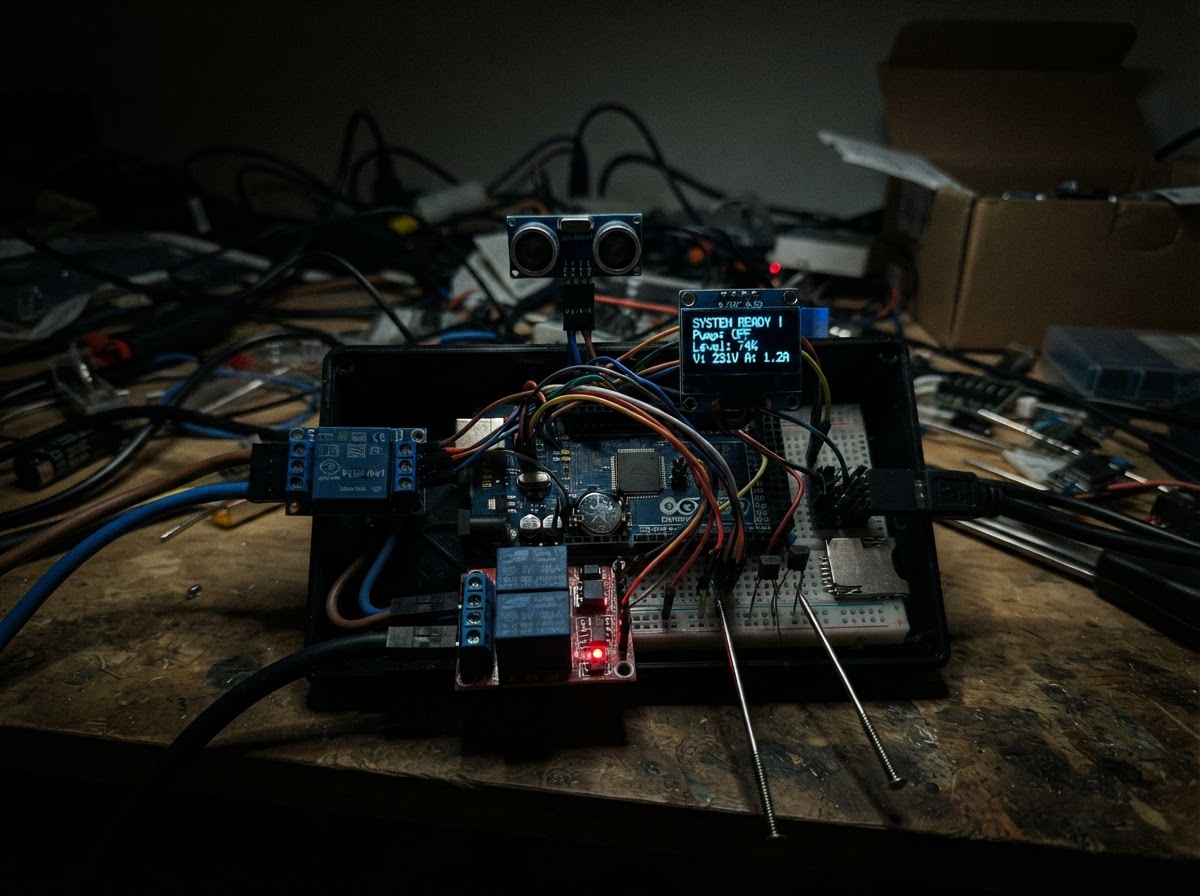
The Smart Water Pump Controller automates residential water pump operation using real-time monitoring and safety protection. Built around an ESP32 microcontroller, it combines AC power metering (PZEM-004T), ultrasonic tank level sensing (JSN-SR04T), water quality detection (stainless steel probes), and precise timekeeping (DS3231 RTC) to prevent dry-run damage, over-voltage faults, and tank overflow. A 30A relay module handles pump switching while Blynk cloud integration enables remote monitoring and control from any smartphone.
This guide provides a complete wiring diagram, detailed parts list, and step-by-step assembly instructions with emphasis on safety isolation between high-voltage mains and low-voltage logic circuits. The base firmware includes pump automation logic, threshold-based protection, and energy tracking. Expansion headers are pre-positioned for future upgrades like temperature monitoring, SD card logging, and OLED display integration without requiring PCB redesign.
Wiring diagram

Gather all the parts
Assemble it in 10 steps
1. Safety First — Power Isolation
Before starting ANY wiring, ensure the 220V mains supply is completely switched OFF at the circuit breaker. Use a multimeter to verify zero voltage. Keep the AC section and DC section visually separated on your workbench the entire time.
- Use red wire for AC Live, black for AC Neutral, green/yellow for Earth throughout.
- NEVER work on live 220V wiring. Death or severe injury can result.
- A licensed electrician must verify and sign off on all mains connections in your jurisdiction.
2. PCB Zone Planning — High Voltage vs Low Voltage Separation
Your PCB (or enclosure) must have a clear physical barrier between the HIGH VOLTAGE zone and the LOW VOLTAGE zone: HIGH VOLTAGE ZONE (RIGHT side of PCB / enclosure): • PZEM-004T AC terminals (Live In / Neutral In / Live Out / Neutral Out) • Relay 30A screw terminals (NO, COM, NC) • Future magnetic contactor header (HDR_CONTACTOR) • All wires here are 2.5mm² rated for 30A minimum LOW VOLTAGE ZONE (LEFT side of PCB / enclosure): • ESP32 DevKit V1 • PZEM-004T UART header (VCC/GND/RX/TX) • DS3231 RTC module • JSN-SR04T driver board • BC547 probe transistor circuits • All future upgrade headers (OLED, SD, DS18B20, ZMPT101B) • 5V regulated power supply board ISOLATION GAP: Maintain at least 8mm creepage distance between AC traces/wires and DC traces/wires on the PCB. Use a slot routed in the PCB if possible.
- Never route DC signal traces under or adjacent to AC pads without proper creepage/clearance.
- Use conformal coating on the entire HV zone after testing.
3. Prepare the 5V Power Supply
Use a 5V/3A (or higher) DIN-rail or panel-mount PSU to power all DC components: • PSU 220V IN → Mains Live + Neutral (after the main circuit breaker) • PSU 5V OUT (+) → Common 5V rail on PCB • PSU 5V OUT (−) → Common GND rail on PCB The ESP32 is then powered from the 5V rail via its VIN pin (the ESP32 onboard regulator converts to 3.3V).
- A MEAN WELL HDR-15-5 or similar is ideal for DIN-rail enclosures.
- Add a 470µF/10V electrolytic capacitor across the 5V rail near the ESP32 to absorb relay switching noise.
4. Wire the PZEM-004T (AC Mains Side)
The PZEM-004T has TWO connection types: AC MAINS TERMINALS (HIGH VOLTAGE — do this last, with power OFF): 1. PZEM 'L' (input) → Mains 220V Live wire (after circuit breaker) 2. PZEM 'N' (input) → Mains 220V Neutral wire 3. PZEM 'L' (output) → Relay COM screw terminal 4. PZEM 'N' (output) → Pump Neutral terminal directly (The CT clamp clips around the Live output wire — DO NOT open the CT clamp under load) UART HEADER (LOW VOLTAGE — 5-pin JST or 4-pin header): • PZEM VCC → 5V rail • PZEM GND → GND rail • PZEM TX → ESP32 GPIO16 (Serial2 RX) • PZEM RX → ESP32 GPIO17 (Serial2 TX)
- Route the CT clamp cable away from the AC terminal wires to reduce EMI pickup.
- The PZEM AC terminals carry lethal mains voltage. Use 2.5mm² wire rated for the pump current.
- Clip the CT clamp fully closed around ONLY the Live output wire — not both Live+Neutral together.
5. Wire the 30A Relay Module
CONTROL SIDE (Low Voltage): • Relay VCC → 5V rail • Relay GND → GND rail • Relay IN → ESP32 GPIO27 (Most relay modules with optocouplers accept 3.3V logic on IN — verify your module's spec; if HIGH = 3.3V is not enough, add a 2N2222 transistor driver) LOAD SIDE (High Voltage — power OFF): • Relay COM → PZEM Live Output wire • Relay NO → Pump Live terminal • Leave NC unconnected FUTURE MAGNETIC CONTACTOR HEADER: • Solder a 2-pin screw-terminal header on the PCB, connected in PARALLEL with the relay NO + COM. • Silkscreen label: 'CONT-NO' and 'CONT-COM' • When upgrading: connect contactor coil wires to this header; remove the direct pump wire from relay NO.
- Ensure the relay is rated for at least the pump's starting surge current (typically 6-8× rated current).
- Use a flyback diode (1N4007) across the contactor coil when upgrading.
6. Install the JSN-SR04T in the Overhead Tank
PHYSICAL INSTALLATION IN TANK: 1. Drill a 22mm hole in the TOP CENTER of the tank lid/cover. 2. Thread the JSN-SR04T waterproof transducer (the small cylinder on a cable) through the hole from inside. 3. Fix it with the supplied nut so the face points STRAIGHT DOWN toward the water surface. 4. The transducer cable runs UP through the hole and connects to the driver board OUTSIDE the tank. 5. Position the transducer face 10–15cm below the tank ceiling so it clears the minimum detection range. DRIVER BOARD (inside the enclosure, LOW VOLTAGE ZONE): • VCC → 5V rail • GND → GND rail • TRIG → ESP32 GPIO25 • ECHO → ESP32 GPIO26 (ECHO output is 5V logic — the JSN-SR04T is powered at 5V. On ESP32, GPIO26 is INPUT with max 3.6V. ADD a voltage divider: 10K from ECHO to GPIO26, 20K from GPIO26 to GND, to bring 5V echo down to ~3.3V.)
- Set TANK_HEIGHT_CM and SENSOR_OFFSET_CM in the firmware to match your actual tank dimensions.
- Do NOT let water submerge the driver board — only the transducer head is waterproof.
- The ESP32 GPIO26 is a 3.3V input — always use a voltage divider on the ECHO line.
7. Install the SS Probe Sets (BC547 Circuits)
OVERVIEW: Each probe set consists of 2 stainless steel rods in a T-joint, processed via a BC547 NPN transistor circuit. CIRCUIT PER PROBE SET: • 5V → 10KΩ (R_common) → SS Common rod • SS Sense rod → 10KΩ (R_base) → BC547 Base • BC547 Emitter → GND • BC547 Collector → 4.7KΩ pullup → 3.3V • BC547 Collector (junction with 4.7K) → ESP32 GPIO Logic: When water bridges the rods, base current flows → transistor saturates → collector = LOW (water detected) PROBE SET A — WASA LINE (GPIO32): Install in a vertical T-joint on the incoming WASA supply pipe, where water presence indicates supply is flowing. Rod spacing: ~1cm apart, sealed with waterproof silicone around the T-joint entry points. PROBE SET B — SUCTION PIPE (GPIO33): Install in a vertical T-joint just above the pump suction inlet or sump pit. This detects if the source tank/sump has water — protects against dry-running the pump. PHYSICAL INSTALLATION: 1. Cut a T-joint fitting into the pipe using appropriate unions. 2. Drill 2× 6mm holes in the T-joint body, 20mm apart vertically. 3. Insert M5 stainless steel rods (food-grade SS316 preferred) through compression fittings. 4. Connect wires to rod ends with stainless clamps — do NOT use copper crimps (corrosion). 5. Seal all entries with self-amalgamating tape + silicone.
- Use 10K current-limiting resistors in series with the probe common rod to slow electrolytic corrosion.
- Consider AC-coupled probe circuits for zero-electrolysis (advanced future upgrade).
- Use ONLY stainless steel (SS304 or SS316) rods — copper or galvanized rods corrode and contaminate water.
- Never use more than 5V on probe circuits — higher voltages electrolyze the water and corrode rods faster.
8. Install the DS3231 RTC Module
• VIN → 3.3V rail (DS3231 works at 3.3V — no level shifting needed for I2C with 3.3V pullups) • GND → GND rail • SDA → ESP32 GPIO21 • SCL → ESP32 GPIO22 • Insert a CR1220 coin cell into the module's battery holder for power-loss timekeeping. • The module has onboard 10KΩ I2C pullups — do NOT add additional pullups on the same bus.
- DS3231 I2C address is 0x68. The future OLED will use 0x3C — no conflict.
9. Connect Future Upgrade Pin Headers (Leave Unpopulated)
Solder these headers onto the PCB NOW even if the modules aren't installed yet — doing it later requires re-opening the enclosure. HDR_OLED (4-pin, 2.54mm): VCC(3.3V) | GND | SDA(21) | SCL(22) → Place near DS3231 on the I2C bus. Leave header empty; cap it with a dust cover. HDR_SDCARD (6-pin, 2.54mm): VCC(3.3V) | GND | MOSI(23) | MISO(19) | SCK(18) | CS(13) → Solder the 4.7K DS18B20 1-Wire pullup resistor (R_DS18B20) between pin 1 (3.3V) and the DATA pin on HDR_DS18B20 during PCB assembly — it is small and easier to solder now. HDR_DS18B20 (3-pin, 2.54mm): VCC(3.3V) | GND | DATA(4) → Include the 4.7K pullup resistor pad on the PCB between VCC and DATA. HDR_ZMPT101B (3-pin, 2.54mm): VCC(5V) | GND | AOUT(34) → ADC pin GPIO34 is INPUT-ONLY, which is perfect for this analog use. HDR_CONTACTOR (2-pin screw terminal, 5.08mm pitch): NO | COM → Bridge in parallel with relay NO and COM screw terminals. → Label silkscreen: 'CONTACTOR COIL OUTPUT — 220V MAX'
- Use right-angle headers if the modules will mount flush to the PCB, or vertical headers for plug-in modules.
- Silkscreen every header with pin names and voltage clearly — critical for future-proof maintenance.
10. Final Wiring Check and Power-On Test
BEFORE APPLYING 220V: 1. With power OFF, use a multimeter (continuity mode) to verify: - 5V rail: no short to GND - All GPIO connections match the firmware pin definitions - Relay COM and NO are isolated from each other (NO = open circuit when de-energized) 2. Apply 5V DC first (power supply only — no mains yet). - Open Serial Monitor in Schematik at 115200 baud. - Confirm: DS3231 OK, PZEM readings appear (may show 0V until AC connected). - Trigger the relay manually via Blynk V0 button — you should hear the relay click. 3. Apply 220V mains ONLY after DC tests pass, with the pump disconnected. - Verify PZEM reads correct mains voltage (~220-240V). 4. Connect pump and run a full cycle test.
- Use the Blynk V7 status widget to confirm the controller state machine is responding correctly before connecting the pump.
- Have a qualified electrician present when applying 220V for the first time.
- Keep an insulated safety mat under your feet when working near live mains.
Review all connections
1. Connections between "pzem" and "ESP32"
2. Connections between "ultrasonic" and "ESP32"
3. Connections between "rtc" and "ESP32"
4. Connections between "relay" and "ESP32"
5. Connections between "probe_wasa" and "ESP32"
6. Connections between "probe_suction" and "ESP32"
7. Connections between "hdr_oled" and "ESP32"
8. Connections between "hdr_sdcard" and "ESP32"
9. Connections between "hdr_ds18b20" and "ESP32"
10. Connections between "hdr_zmpt101b" and "ESP32"
Deploy the firmware
#include <Arduino.h>
// ============================================================
//  Smart Water Pump Controller  —  ESP32 + Blynk
//  Base Model: PZEM-004T | JSN-SR04T | SS Probes | DS3231
// ============================================================
//  FUTURE UPGRADE PINS (defined but not active in base code)
//  - DS18B20 temperature  :  GPIO 4  (1-Wire, 4.7K pullup on PCB)
//  - ZMPT101B AC voltage  :  GPIO 34 (ADC, unpopulated header)
//  - SD Card CS           :  GPIO 13 (SPI, unpopulated header)
//  - OLED I2C             :  GPIO 21/22 (shares bus with RTC)
// ============================================================

// ── Blynk credentials ───────────────────────────────────────
// Replace with your own from the Blynk app
#define BLYNK_TEMPLATE_ID   "TMPLxxxxxxxxxx"
#define BLYNK_TEMPLATE_NAME "SmartPumpCtrl"
#define BLYNK_AUTH_TOKEN    "YourBlynkAuthTokenHere"

// ── Blynk Virtual Pin Map ───────────────────────────────────
// V0  → Pump ON/OFF button (Blynk → device)
// V1  → Voltage (V) display
// V2  → Current (A) display
// V3  → Power (W) display
// V4  → Energy (kWh) display
// V5  → Tank level % display
// V6  → Time ON (HH:MM:SS) display
// V7  → Status string (RUNNING / DRY-RUN / PROTECTION etc.)
// V8  → Over-voltage threshold (Blynk → device), default 250V
// V9  → Under-voltage threshold (Blynk → device), default 180V
// V10 → Tank FULL threshold % (Blynk → device), default 90%
// V11 → Tank LOW threshold %  (Blynk → device), default 20%
// V12 → Current time from RTC (display)
// V13 → WASA probe raw state (0=water / 1=dry)
// V14 → Suction probe raw state (0=water / 1=dry)

// ── Includes ────────────────────────────────────────────────
#define BLYNK_PRINT Serial
#include <WiFi.h>
#include <BlynkSimpleEsp32.h>
#include <PZEM004Tv30.h>
#include <NewPing.h>
#include <Wire.h>
#include <RTClib.h>

// ── WiFi credentials ────────────────────────────────────────

// Forward declarations
void setPump(bool on);
String formatTime(unsigned long ms);
void pollSensors();

const char* WIFI_SSID     = "YourWiFiSSID";
const char* WIFI_PASSWORD = "YourWiFiPassword";

// ── Hardware Pin Definitions ────────────────────────────────
// Active in base code:
#define PZEM_RX_PIN      16   // Serial2 RX ← PZEM TX
#define PZEM_TX_PIN      17   // Serial2 TX → PZEM RX
#define TRIG_PIN         25   // JSN-SR04T TRIG
#define ECHO_PIN         26   // JSN-SR04T ECHO
#define RELAY_PIN        27   // 5V Relay IN (LOW = ON via optocoupler)
#define PROBE_WASA_PIN   32   // BC547 collector — WASA line probe
#define PROBE_SUCTION_PIN 33  // BC547 collector — Suction/sump probe

// Reserved for future population (no code using them in base):
#define DS18B20_PIN       4   // FUTURE: 1-Wire temp sensors (4.7K pullup on PCB)
#define ZMPT101B_PIN     34   // FUTURE: AC voltage analog sensor
#define SD_CS_PIN        13   // FUTURE: SD card SPI CS
// OLED & RTC share I2C GPIO21(SDA)/GPIO22(SCL) — OLED header already parallel

// ── Constants ───────────────────────────────────────────────
#define TANK_HEIGHT_CM         200   // Total tank height in cm — ADJUST FOR YOUR TANK
#define SENSOR_OFFSET_CM        10   // Distance from sensor face to max-water surface
#define MAX_DISTANCE_CM        250   // NewPing max range
#define DRY_RUN_COOLDOWN_MS  300000UL // 5-minute dry-run cooldown (ms)
#define BLYNK_UPDATE_MS       2000UL  // Blynk push interval
#define SENSOR_UPDATE_MS       500UL  // Local sensor poll interval

// ── Global Objects ──────────────────────────────────────────
PZEM004Tv30 pzem(Serial2, PZEM_RX_PIN, PZEM_TX_PIN);
NewPing sonar(TRIG_PIN, ECHO_PIN, MAX_DISTANCE_CM);
RTC_DS3231 rtc;
BlynkTimer timer;

// ── State Variables ─────────────────────────────────────────
bool pumpEnabled      = false;   // User intent from Blynk
bool pumpRunning      = false;   // Actual relay state
bool dryRunLocked     = false;   // In cooldown after dry-run
bool overvoltProtect  = false;   // OVP triggered
bool undervoltProtect = false;   // UVP triggered

unsigned long dryRunLockTime = 0;  // When dry-run cooldown started
unsigned long pumpOnTime     = 0;  // millis() when pump last started
unsigned long pumpOnAccum    = 0;  // Accumulated ON-time this session (ms)

// Adjustable thresholds (can be changed via Blynk sliders)
float threshOV   = 250.0f;  // Over-voltage limit (V)
float threshUV   = 180.0f;  // Under-voltage limit (V)
int   threshFull = 90;      // Tank full % → stop pump
int   threshLow  = 20;      // Tank low %  → auto-start pump

// Live PZEM readings
float pzemVoltage  = 0, pzemCurrent = 0;
float pzemPower    = 0, pzemEnergy  = 0;
float pzemFreq     = 0, pzemPF      = 0;

// Tank level
int tankPercent = 0;

// ── Helper: Relay Control ────────────────────────────────────
void setPump(bool on) {
  if (on && !pumpRunning) {
    digitalWrite(RELAY_PIN, LOW);   // Active LOW relay
    pumpOnTime   = millis();
    pumpRunning  = true;
  } else if (!on && pumpRunning) {
    digitalWrite(RELAY_PIN, HIGH);
    pumpOnAccum += millis() - pumpOnTime;
    pumpRunning  = false;
  }
}

// ── Helper: Format seconds to HH:MM:SS ──────────────────────
String formatTime(unsigned long ms) {
  unsigned long secs = ms / 1000;
  unsigned int h = secs / 3600;
  unsigned int m = (secs % 3600) / 60;
  unsigned int s = secs % 60;
  char buf[12];
  snprintf(buf, sizeof(buf), "%02u:%02u:%02u", h, m, s);
  return String(buf);
}

// ── Sensor Poll ─────────────────────────────────────────────
void pollSensors() {
  // — PZEM-004T —
  float v = pzem.voltage();
  float i = pzem.current();
  float p = pzem.power();
  float e = pzem.energy();
  float f = pzem.frequency();
  float pf = pzem.pf();

  if (!isnan(v)) pzemVoltage  = v;
  if (!isnan(i)) pzemCurrent  = i;
  if (!isnan(p)) pzemPower    = p;
  if (!isnan(e)) pzemEnergy   = e;
  if (!isnan(f)) pzemFreq     = f;
  if (!isnan(pf)) pzemPF      = pf;

  // Over/Under Voltage Protection
  if (pzemVoltage > 0) {
    overvoltProtect  = (pzemVoltage > threshOV);
    undervoltProtect = (pzemVoltage < threshUV && pzemVoltage > 50); // ignore 0V (no reading)
  }

  // — JSN-SR04T Tank Level —
  unsigned int distCm = sonar.ping_cm();
  if (distCm > 0 && distCm < MAX_DISTANCE_CM) {
    int waterCm = TANK_HEIGHT_CM - (distCm - SENSOR_OFFSET_CM);
    waterCm = constrain(waterCm, 0, TANK_HEIGHT_CM);
    tankPercent = map(waterCm, 0, TANK_HEIGHT_CM, 0, 100);
  }

  // — SS Probes (BC547 NPN: HIGH = dry, LOW = water present) —
  bool wasaWater    = (digitalRead(PROBE_WASA_PIN)   == LOW);  // WASA supply present
  bool suctionWater = (digitalRead(PROBE_SUCTION_PIN) == LOW); // Sump/suction has water

  // Dry-run cooldown management
  if (dryRunLocked) {
    if (millis() - dryRunLockTime >= DRY_RUN_COOLDOWN_MS) {
      dryRunLocked = false;
      Serial.println("[INFO] Dry-run cooldown expired, allowing retry.");
    }
  }

  // — Pump Decision Logic —
  // Priority: OVP/UVP > Dry-run lock > Tank full > User intent + probes
  bool shouldRun = false;
  if (!overvoltProtect && !undervoltProtect && !dryRunLocked) {
    if (pumpEnabled) {
      // Auto-stop if tank is full
      if (tankPercent >= threshFull) {
        shouldRun = false;
        pumpEnabled = false;
        Blynk.virtualWrite(V0, 0);
      } else if (!wasaWater) {
        // WASA line dry — trigger dry-run protection
        if (pumpRunning) {
          Serial.println("[WARN] WASA dry-run detected! Locking out for 5 min.");
          dryRunLocked    = true;
          dryRunLockTime  = millis();
          shouldRun       = false;
        }
      } else if (!suctionWater) {
        // Suction sump dry — trigger dry-run protection
        if (pumpRunning) {
          Serial.println("[WARN] Suction dry-run detected! Locking out for 5 min.");
          dryRunLocked    = true;
          dryRunLockTime  = millis();
          shouldRun       = false;
        }
      } else {
        shouldRun = true;
      }
    }
    // Auto-start if tank is low and WASA + suction both have water
    if (!pumpEnabled && tankPercent <= threshLow && wasaWater && suctionWater) {
      shouldRun   = true;
      pumpEnabled = true;
      Blynk.virtualWrite(V0, 1);
    }
  }

  setPump(shouldRun);

  // Status string
  String status;
  if (overvoltProtect)      status = "⚡ OVP TRIP";
  else if (undervoltProtect) status = "⚡ UVP TRIP";
  else if (dryRunLocked)    status = "🔒 DRY-RUN COOLDOWN";
  else if (pumpRunning)      status = "✅ PUMP RUNNING";
  else if (!pumpEnabled)     status = "⏸ STANDBY";
  else                       status = "⚠ WAITING";

  // — Blynk Updates (write here to avoid second timer collision) —
  Blynk.virtualWrite(V1, pzemVoltage);
  Blynk.virtualWrite(V2, pzemCurrent);
  Blynk.virtualWrite(V3, pzemPower);
  Blynk.virtualWrite(V4, pzemEnergy);
  Blynk.virtualWrite(V5, tankPercent);
  Blynk.virtualWrite(V7, status);
  Blynk.virtualWrite(V13, wasaWater    ? 0 : 1);
  Blynk.virtualWrite(V14, suctionWater ? 0 : 1);

  // Pump ON time
  unsigned long totalOnMs = pumpOnAccum + (pumpRunning ? (millis() - pumpOnTime) : 0);
  Blynk.virtualWrite(V6, formatTime(totalOnMs));

  // RTC time
  DateTime now = rtc.now();
  char tbuf[10];
  snprintf(tbuf, sizeof(tbuf), "%02d:%02d:%02d", now.hour(), now.minute(), now.second());
  Blynk.virtualWrite(V12, String(tbuf));

  // Serial debug
  Serial.printf("[PZEM] V=%.1fV  I=%.3fA  P=%.1fW  E=%.3fkWh  F=%.1fHz  PF=%.2f\n",
                pzemVoltage, pzemCurrent, pzemPower, pzemEnergy, pzemFreq, pzemPF);
  Serial.printf("[TANK] %d cm → %d%%  [WASA:%s SUCT:%s] [PUMP:%s]\n",
                distCm, tankPercent,
                wasaWater ? "OK" : "DRY", suctionWater ? "OK" : "DRY",
                pumpRunning ? "ON" : "OFF");
}

// ── Blynk Callbacks ─────────────────────────────────────────
// V0 — Manual Pump Button
BLYNK_WRITE(V0) {
  int val = param.asInt();
  pumpEnabled = (val == 1);
  if (!pumpEnabled) setPump(false);   // Immediate OFF on manual press
  Serial.printf("[BLYNK] Manual pump %s\n", pumpEnabled ? "ENABLED" : "DISABLED");
}

// V8 — Over-voltage threshold
BLYNK_WRITE(V8) { threshOV   = param.asFloat(); }

// V9 — Under-voltage threshold
BLYNK_WRITE(V9) { threshUV   = param.asFloat(); }

// V10 — Tank full %
BLYNK_WRITE(V10) { threshFull = param.asInt(); }

// V11 — Tank low %
BLYNK_WRITE(V11) { threshLow  = param.asInt(); }

// ── Setup ────────────────────────────────────────────────────
void setup() {
  Serial.begin(115200);
  Serial.println("\n=== Smart Water Pump Controller ===");

  // Relay — default OFF (HIGH for active-low relay)
  pinMode(RELAY_PIN, OUTPUT);
  digitalWrite(RELAY_PIN, HIGH);

  // Probes — internal pullup (BC547 collector already has 4.7K on PCB)
  // Using INPUT since external pullups are on PCB; internal disabled to avoid conflict
  pinMode(PROBE_WASA_PIN,    INPUT);
  pinMode(PROBE_SUCTION_PIN, INPUT);

  // I2C + RTC
  Wire.begin(21, 22);
  if (!rtc.begin()) {
    Serial.println("[ERROR] DS3231 RTC not found! Check wiring.");
  } else {
    if (rtc.lostPower()) {
      Serial.println("[RTC] Lost power — setting time to compile time.");
      rtc.adjust(DateTime(F(__DATE__), F(__TIME__)));
    }
    Serial.println("[RTC] DS3231 OK");
  }

  // Blynk
  Blynk.begin(BLYNK_AUTH_TOKEN, WIFI_SSID, WIFI_PASSWORD);

  // Push thresholds to Blynk on startup
  Blynk.virtualWrite(V8,  threshOV);
  Blynk.virtualWrite(V9,  threshUV);
  Blynk.virtualWrite(V10, threshFull);
  Blynk.virtualWrite(V11, threshLow);

  // Timer: poll sensors + push to Blynk every 2 s
  timer.setInterval(2000L, pollSensors);

  Serial.println("[INFO] Setup complete — entering loop.");
}

// ── Loop ─────────────────────────────────────────────────────
void loop() {
  Blynk.run();
  timer.run();
}

// ============================================================
//  FUTURE UPGRADE STUBS  (un-comment when headers populated)
// ============================================================

/* ── DS18B20 Temperature ─────────────────────────────────────
#include <OneWire.h>
#include <DallasTemperature.h>
OneWire oneWire(DS18B20_PIN);
DallasTemperature tempSensors(&oneWire);
// In setup():   tempSensors.begin();
// In pollSensors() or separate timer:
//   tempSensors.requestTemperatures();
//   float t1 = tempSensors.getTempCByIndex(0);
//   float t2 = tempSensors.getTempCByIndex(1);
//   Blynk.virtualWrite(V15, t1);
//   Blynk.virtualWrite(V16, t2);
*/

/* ── ZMPT101B AC Voltage Analog ─────────────────────────────
// Read ADC, calculate RMS, cross-check with PZEM reading
// int rawVal = analogRead(ZMPT101B_PIN);
// float zmptVoltage = map(rawVal, 0, 4095, 0, 300); // calibrate
// Blynk.virtualWrite(V17, zmptVoltage);
*/

/* ── SD Card Data Logging ───────────────────────────────────
#include <SD.h>
// In setup():  SD.begin(SD_CS_PIN);
// Log to CSV:  File f = SD.open("/log.csv", FILE_APPEND);
//              f.printf("%s,%.1f,%.3f,%.1f,%.3f,%d\n",
//                       timeStr, pzemVoltage, pzemCurrent,
//                       pzemPower, pzemEnergy, tankPercent);
//              f.close();
*/

/* ── OLED SSD1306 / SH1106 ──────────────────────────────────
#include <Adafruit_SSD1306.h>
Adafruit_SSD1306 display(128, 64, &Wire, -1);
// In setup():  display.begin(SSD1306_SWITCHCAPVCC, 0x3C);
// In loop():   display.clearDisplay();
//              display.printf("V: %.1f W: %.0f", pzemVoltage, pzemPower);
//              display.display();
*/

/* ── Magnetic Contactor ─────────────────────────────────────
// No code change needed. Wire relay NO+COM screw terminals
// to the HDR_CONTACTOR pin header on the PCB.
// Contactor coil: one wire to NO header pin, other to COM header pin.
// The relay switches the 220V coil energization line.
*/
Remix this project
Make it yours in one click
Open a full copy of this project in your own Schematik workspace — diagram, code, parts, and assembly steps included. Swap the sensor, add features, or redesign the whole thing with AI. The author's original stays untouched.