Community project
SmartBand Assistive Safety Wearable
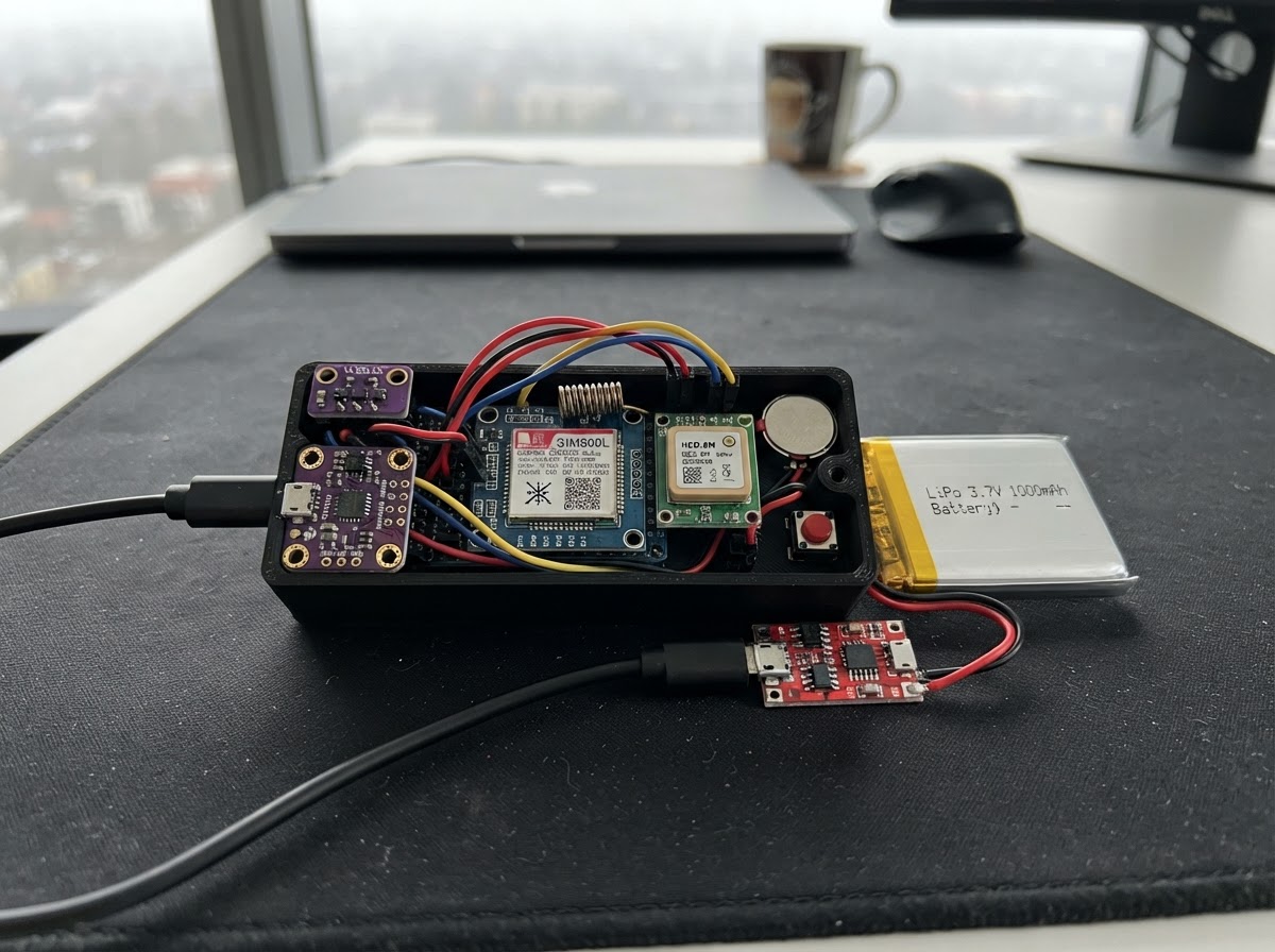
SmartBand is a wearable safety device designed to assist visually impaired users by providing real-time obstacle detection, fall detection, and emergency alerting. Built around an ESP32 microcontroller, it combines a time-of-flight distance sensor for haptic feedback, a 6-axis motion sensor for fall detection, GPS positioning, and GSM connectivity to send emergency alerts with location data to caregivers.
This guide provides a complete parts list, wiring diagram, and step-by-step assembly instructions for building the device from scratch. You'll learn how to integrate multiple sensors on a shared I²C bus, configure the GSM module for SMS alerts, calibrate the boost converter for stable power delivery, and upload the firmware that enables distance sensing, fall detection, and emergency notifications via a simple push button or automatic triggers.
Wiring diagram

Gather all the parts
Assemble it in 10 steps
1. Gather all parts & tools
Lay out: ESP32 DevKit v1, VL53L1X ToF breakout, MPU-6050 GY-521 breakout, NEO-6M GPS module, SIM800L GSM module with antenna, RCD0820 coin vibration motor, TP4056 LiPo charger module, MT3608 boost converter module, LiPo 3.7V 1000mAh battery, 2N2222 (or BC547) NPN transistor, 1N4001 diode, 470µF 10V electrolytic capacitor, resistors (1kΩ ×1, 10kΩ ×1, 22kΩ ×1), push button, jumper wires, breadboard or perfboard, JST connector (for battery). Tools: soldering iron, multimeter.
- Keep the SIM card inserted into SIM800L before powering.
- Verify the MT3608 output is set to ~4.2V BEFORE connecting SIM800L.
- Never connect the LiPo battery until all wiring is verified with a multimeter.
2. Pre-set the MT3608 boost converter to 4.2V
Connect the MT3608 input to a 3.7V bench supply. Measure the output with a multimeter while slowly turning the onboard trim potentiometer clockwise until output reads 4.0–4.2V. Disconnect the bench supply. This step is critical — too high a voltage will damage the SIM800L.
- Do not set boost output above 4.4V — SIM800L maximum is 4.4V. 4.0–4.2V is ideal.
- Always pre-set the boost voltage BEFORE wiring to SIM800L.
3. Wire the power chain
1. Solder the LiPo JST connector to the TP4056 B+ and B- pads. 2. Connect TP4056 OUT+ to ESP32 VIN (the 5V-tolerant power input pin). Connect TP4056 OUT- to ESP32 GND. 3. Tap TP4056 B+ (battery side) also to MT3608 VIN. Connect MT3608 GND to ESP32 GND. 4. Connect MT3608 VOUT to SIM800L VCC. 5. Solder a 470µF electrolytic capacitor across SIM800L VCC and GND (positive leg to VCC) as close to the module as possible.
- The ESP32 onboard 3.3V LDO accepts 4.5–12V on VIN, so the TP4056 4.2V output is within spec.
- The 470µF cap handles SIM800L's 2A TX burst spikes.
- Polarity: electrolytic capacitors will fail or explode if installed backwards. Verify + leg to VCC.
- Check TP4056 OUT+ voltage: should be 3.7–4.2V depending on battery charge.
4. Wire the I²C bus — VL53L1X ToF Sensor
1. VL53L1X VIN → ESP32 3.3V pin 2. VL53L1X GND → GND 3. VL53L1X SDA → ESP32 GPIO21 4. VL53L1X SCL → ESP32 GPIO22 5. VL53L1X XSHUT → ESP32 GPIO4 (pulled HIGH in firmware to keep sensor active)
- The SparkFun/Pololu VL53L1X breakout includes onboard pull-ups — no external resistors needed.
- Mount the sensor on the wrist band so it points outward away from the hand.
5. Wire the MPU-6050 (shares I²C bus)
1. MPU-6050 VIN → ESP32 3.3V (accepts 3–5V) 2. MPU-6050 GND → GND 3. MPU-6050 SDA → ESP32 GPIO21 (shared with ToF) 4. MPU-6050 SCL → ESP32 GPIO22 (shared with ToF) 5. MPU-6050 INT → ESP32 GPIO33 6. Leave the AD0 pin unconnected (I²C address 0x68, different from VL53L1X 0x29 — no conflict).
- Both sensors share the I²C bus without conflict: VL53L1X=0x29, MPU-6050=0x68.
- If the INT line stays high, add a 10kΩ pull-down resistor from GPIO33 to GND.
6. Wire the NEO-6M GPS module
1. NEO-6M VCC → ESP32 3.3V 2. NEO-6M GND → GND 3. NEO-6M TX → ESP32 GPIO16 (RX2) 4. NEO-6M RX → ESP32 GPIO17 (TX2, optional — firmware only reads NMEA output)
- Place the GPS module where it has a clear view of the sky for satellite lock.
- First lock takes 1–3 minutes outdoors. A solid blue LED on the module confirms fix.
7. Wire the SIM800L GSM module
1. SIM800L GND → ESP32 GND (common ground) 2. SIM800L TX → ESP32 GPIO26 (direct — 2.8V output is safe for ESP32 3.3V input) 3. ESP32 GPIO25 → Voltage divider IN: - 10kΩ resistor from GPIO25 to a mid-node - 22kΩ resistor from mid-node to GND - Mid-node → SIM800L RX This divides 3.3V × (22/(10+22)) ≈ 2.27V, safely within SIM800L's 2.8V input spec. 4. SIM800L RST → ESP32 GPIO14 5. Attach the GSM antenna to SIM800L's uFL or SMA connector.
- Confirm the SIM card is inserted, unlocked (no PIN lock), and has SMS credits or a data plan.
- The SIM800L's red LED should blink once per second when registered to network.
- Do NOT connect SIM800L VCC directly to ESP32 3.3V — use the MT3608 boost output only.
- Without the 470µF cap, the SIM800L may brown-out the ESP32 during TX bursts.
8. Build the vibration motor driver circuit
On the breadboard or perfboard: 1. NPN transistor (2N2222): Base → 1kΩ resistor → ESP32 GPIO27; Emitter → GND 2. Coin vibration motor M+ → ESP32 3.3V 3. Motor M- → Transistor Collector 4. 1N4001 flyback diode: Anode to Collector (motor M-), Cathode to 3.3V (motor M+) — stripe/band on cathode end The ESP32 GPIO27 drives the transistor base. PWM duty cycle controls vibration intensity.
- The coin motor draws ~100mA peak, well within the 2N2222's 600mA rating.
- Flyback diode is mandatory — without it, motor back-EMF will damage the ESP32 GPIO.
9. Wire the SOS push button
1. One terminal of push button → ESP32 GPIO32 2. Other terminal → GND The firmware uses the internal pull-up on GPIO32; pressing the button pulls it LOW and triggers the SOS interrupt.
- Mount the button on the side of the wristband where the user's thumb rests naturally.
- Test by pressing the button once — you should get 5 rapid vibration pulses and see '[SOS]' in the Serial Monitor.
10. Double-check and power on
Before connecting the battery: 1. Use a multimeter to verify no short between 3.3V and GND rails. 2. Verify no short between the MT3608 VOUT and GND (should read open circuit with no load). 3. Confirm voltage divider mid-node reads ~2.2V when GPIO25 outputs 3.3V (use a simple GPIO test sketch). 4. Connect the LiPo battery to TP4056. 5. The ESP32 should boot; you will see 2 vibration pulses confirming successful startup.
- Use the Schematik Deploy button to flash firmware — no IDE setup needed.
- Open the Serial Monitor at 115200 baud to watch sensor status messages.
- Update CAREGIVER_PHONE in firmware to a real number before the SOS test.
- Do not run the GSM SMS test without a valid SIM and phone number — the modem will fail silently.
- If the ESP32 resets during GSM registration, the 470µF cap may be absent or too small — try 1000µF.
Review all connections
1. Connections between "battery" and "ESP32"
2. Connections between "charger" and "ESP32"
3. Connections between "boost_gsm" and "ESP32"
4. Connections between "tof" and "ESP32"
5. Connections between "imu" and "ESP32"
6. Connections between "gps" and "ESP32"
7. Connections between "gsm" and "ESP32"
8. Connections between "vdiv_gsm" and "ESP32"
9. Connections between "vibration_npn" and "ESP32"
10. Connections between "vibration" and "ESP32"
11. Connections between "sos_btn" and "ESP32"
Deploy the firmware
/*
 * SmartBand — AI-Powered Wrist Wearable for the Visually Impaired
 * ESP32 DevKit v1 Firmware
 *
 * Features:
 *  - VL53L1X ToF distance sensing with distance-proportional vibration feedback
 *  - MPU-6050 fall detection via interrupt (free-fall + shock threshold)
 *  - NEO-6M GPS location acquisition
 *  - SIM800L GSM SMS emergency alert with GPS coordinates
 *  - SOS push button (manual emergency trigger)
 *  - BLE advertising for phone app connectivity (AI classification trigger)
 */

// ─── TinyGSM config (must come before TinyGSM include) ───────────────────────
#define TINY_GSM_MODEM_SIM800
#define TINY_GSM_RX_BUFFER 512

#include <Arduino.h>
#include <Wire.h>
#include <SparkFun_VL53L1X.h>
#include <MPU6050.h>
#include <TinyGsmClient.h>
#include <TinyGPSPlus.h>
#include <BLEDevice.h>
#include <BLEServer.h>
#include <BLEUtils.h>
#include <BLE2902.h>

// ─── Pin Definitions ─────────────────────────────────────────────────────────
#define TOF_XSHUT       4
#define I2C_SDA         21
#define I2C_SCL         22
#define IMU_INT         33
#define GPS_RX_PIN      16   // ESP32 RX2 ← GPS TX
#define GPS_TX_PIN      17   // ESP32 TX2 → GPS RX
#define GSM_RX_PIN      26   // ESP32 RX ← SIM800L TX
#define GSM_TX_PIN      25   // ESP32 TX → voltage divider → SIM800L RX
#define GSM_RST         14
#define VIBRATION_PWM   27
#define SOS_BTN         32

// ─── Constants ────────────────────────────────────────────────────────────────
#define CAREGIVER_PHONE     "+10000000000"  // ← Replace with real number
#define WARN_DIST_MM        1200            // Start vibrating below 1.2 m
#define DANGER_DIST_MM      400             // Danger zone below 0.4 m

#define FALL_ACCEL_THRESHOLD    2.0f        // g — free-fall detection (low)
#define IMPACT_ACCEL_THRESHOLD  2.5f        // g — impact detection (high)
#define FALL_WINDOW_MS          500         // Window to detect impact after free-fall

#define VIB_CHANNEL     0
#define VIB_FREQ        50000
#define VIB_RESOLUTION  8

// BLE UUIDs
#define SERVICE_UUID        "4fafc201-1fb5-459e-8fcc-c5c9c331914b"
#define CHAR_CMD_UUID       "beb5483e-36e1-4688-b7f5-ea07361b26a8"  // Phone → Band
#define CHAR_EVT_UUID       "beb5483e-36e1-4688-b7f5-ea07361b26a9"  // Band → Phone

// ─── Hardware Objects ─────────────────────────────────────────────────────────

// Forward declarations
void bleNotify(const char* msg);
void setVibration(int distMm);
void vibratePulse(int count, int onMs, int offMs, int duty);
bool initGSM();
void sendSMS(const char* message);
void IRAM_ATTR mpuISR();
void IRAM_ATTR sosISR();

SFEVL53L1X tof;
MPU6050     mpu;

HardwareSerial SerialGPS(2);   // UART2 for GPS
HardwareSerial SerialGSM(1);   // UART1 for SIM800L
TinyGsm        modem(SerialGSM);

TinyGPSPlus gps;

// ─── BLE ──────────────────────────────────────────────────────────────────────
BLEServer*          bleServer    = nullptr;
BLECharacteristic*  charCmd      = nullptr;
BLECharacteristic*  charEvt      = nullptr;
bool                bleConnected = false;

// ─── State ────────────────────────────────────────────────────────────────────
volatile bool fallDetected  = false;
volatile bool sosPressed    = false;
bool          gsmReady      = false;
bool          alertSent     = false;

float  lastLat = 0.0, lastLng = 0.0;
char   lastGpsStr[64] = "GPS acquiring...";

unsigned long lastDistUpdate   = 0;
unsigned long lastGpsUpdate    = 0;
unsigned long fallTimestamp    = 0;
unsigned long lastBleNotify    = 0;
unsigned long lastVibUpdate    = 0;

bool inFreeFall = false;

// ─── BLE Callbacks ────────────────────────────────────────────────────────────
class BandServerCallbacks : public BLEServerCallbacks {
  void onConnect(BLEServer* s)    { bleConnected = true;  Serial.println("[BLE] Phone connected"); }
  void onDisconnect(BLEServer* s) {
    bleConnected = false;
    Serial.println("[BLE] Phone disconnected — restarting advertising");
    BLEDevice::startAdvertising();
  }
};

class CmdCharCallbacks : public BLECharacteristicCallbacks {
  void onWrite(BLECharacteristic* c) {
    std::string val = c->getValue();
    if (val.length() == 0) return;
    Serial.printf("[BLE] CMD received: %s\n", val.c_str());

    // "CLASSIFY:<label>" — phone AI result, convert to vibration pattern
    if (val.rfind("CLASSIFY:", 0) == 0) {
      String label = String(val.substr(9).c_str());
      label.toLowerCase();
      if (label.indexOf("vehicle") >= 0 || label.indexOf("car") >= 0) {
        // 3 short rapid pulses = vehicle
        for (int i = 0; i < 3; i++) {
          ledcWrite(VIB_CHANNEL, 200); delay(120);
          ledcWrite(VIB_CHANNEL, 0);   delay(80);
        }
      } else if (label.indexOf("stairs") >= 0 || label.indexOf("step") >= 0) {
        // 1 long pulse = stairs
        ledcWrite(VIB_CHANNEL, 200); delay(600);
        ledcWrite(VIB_CHANNEL, 0);
      } else if (label.indexOf("person") >= 0) {
        // 2 medium pulses = person
        for (int i = 0; i < 2; i++) {
          ledcWrite(VIB_CHANNEL, 180); delay(250);
          ledcWrite(VIB_CHANNEL, 0);   delay(150);
        }
      } else {
        // Generic obstacle: 1 short pulse
        ledcWrite(VIB_CHANNEL, 150); delay(200);
        ledcWrite(VIB_CHANNEL, 0);
      }
    }

    // "SOS_ACK" — caregiver acknowledged via app, cancel repeat
    if (val == "SOS_ACK") {
      alertSent = true;
      Serial.println("[BLE] SOS acknowledged by app.");
    }
  }
};

// ─── Helper: Notify BLE phone ─────────────────────────────────────────────────
void bleNotify(const char* msg) {
  if (bleConnected && charEvt) {
    charEvt->setValue(msg);
    charEvt->notify();
  }
}

// ─── Helper: Vibrate with distance-proportional pattern ──────────────────────
void setVibration(int distMm) {
  if (distMm > WARN_DIST_MM || distMm <= 0) {
    ledcWrite(VIB_CHANNEL, 0);
    return;
  }
  // Map distance linearly: 1200mm → duty 60, 400mm → duty 230 (max feels)
  int duty = map(constrain(distMm, DANGER_DIST_MM, WARN_DIST_MM),
                 WARN_DIST_MM, DANGER_DIST_MM, 60, 230);
  ledcWrite(VIB_CHANNEL, duty);
}

// ─── Helper: Pulse vibration N times ─────────────────────────────────────────
void vibratePulse(int count, int onMs, int offMs, int duty = 220) {
  for (int i = 0; i < count; i++) {
    ledcWrite(VIB_CHANNEL, duty); delay(onMs);
    ledcWrite(VIB_CHANNEL, 0);   delay(offMs);
  }
}

// ─── Helper: Init SIM800L modem ──────────────────────────────────────────────
bool initGSM() {
  Serial.println("[GSM] Resetting modem...");
  digitalWrite(GSM_RST, LOW);
  delay(200);
  digitalWrite(GSM_RST, HIGH);
  delay(3000);

  SerialGSM.begin(9600, SERIAL_8N1, GSM_RX_PIN, GSM_TX_PIN);
  delay(1000);

  Serial.println("[GSM] Initialising TinyGSM...");
  if (!modem.restart()) {
    Serial.println("[GSM] Restart failed — trying init()");
    if (!modem.init()) {
      Serial.println("[GSM] Init failed");
      return false;
    }
  }
  String info = modem.getModemInfo();
  Serial.printf("[GSM] Modem: %s\n", info.c_str());

  Serial.println("[GSM] Waiting for network...");
  for (int i = 0; i < 30; i++) {
    if (modem.waitForNetwork(2000)) {
      Serial.println("[GSM] Network registered");
      return true;
    }
    Serial.print(".");
  }
  Serial.println("\n[GSM] Network timeout");
  return false;
}

// ─── Helper: Send SMS ─────────────────────────────────────────────────────────
void sendSMS(const char* message) {
  if (!gsmReady) {
    Serial.println("[GSM] Not ready, skipping SMS");
    return;
  }
  Serial.printf("[GSM] Sending SMS to %s\n", CAREGIVER_PHONE);
  bool ok = modem.sendSMS(CAREGIVER_PHONE, message);
  Serial.printf("[GSM] SMS %s\n", ok ? "SENT" : "FAILED");
}

// ─── IRAM ISR: MPU6050 Interrupt ─────────────────────────────────────────────
void IRAM_ATTR mpuISR() {
  // ISR flags the main loop; detailed motion state is read there
  fallDetected = true;
}

// ─── IRAM ISR: SOS Button ─────────────────────────────────────────────────────
void IRAM_ATTR sosISR() {
  sosPressed = true;
}

// ─── Setup ────────────────────────────────────────────────────────────────────
void setup() {
  Serial.begin(115200);
  Serial.println("\n=== SmartBand booting ===");

  // Vibration PWM
  ledcSetup(VIB_CHANNEL, VIB_FREQ, VIB_RESOLUTION);
  ledcAttachPin(VIBRATION_PWM, VIB_CHANNEL);
  ledcWrite(VIB_CHANNEL, 0);

  // SOS button (internal pull-up, falling edge ISR)
  pinMode(SOS_BTN, INPUT_PULLUP);
  attachInterrupt(digitalPinToInterrupt(SOS_BTN), sosISR, FALLING);

  // GSM reset pin
  pinMode(GSM_RST, OUTPUT);
  digitalWrite(GSM_RST, HIGH);

  // I2C — ToF + MPU
  Wire.begin(I2C_SDA, I2C_SCL);

  // VL53L1X
  pinMode(TOF_XSHUT, OUTPUT);
  digitalWrite(TOF_XSHUT, HIGH);
  delay(10);
  if (tof.begin() == false) {
    Serial.println("[TOF] Sensor not detected — check wiring");
  } else {
    tof.setDistanceModeShort();           // Up to 1.3 m, better in ambient light
    tof.setTimingBudgetInMs(50);          // 50 ms timing budget
    tof.setIntermeasurementPeriod(100);   // 100 ms between measurements
    tof.startRanging();
    Serial.println("[TOF] VL53L1X ready");
  }

  // MPU-6050
  mpu.initialize();
  if (!mpu.testConnection()) {
    Serial.println("[IMU] MPU6050 not detected — check wiring");
  } else {
    Serial.println("[IMU] MPU6050 ready");
    // Configure motion interrupt: free-fall detection
    mpu.setMotionDetectionThreshold(2);    // ~16mg per count
    mpu.setMotionDetectionDuration(40);    // 40 ms hold
    mpu.setMotionDetectionControlActiveLow(false);
    mpu.setIntMotionEnabled(true);
    pinMode(IMU_INT, INPUT);
    attachInterrupt(digitalPinToInterrupt(IMU_INT), mpuISR, RISING);
  }

  // GPS UART
  SerialGPS.begin(9600, SERIAL_8N1, GPS_RX_PIN, GPS_TX_PIN);
  Serial.println("[GPS] UART started");

  // GSM
  gsmReady = initGSM();

  // BLE setup
  BLEDevice::init("SmartBand");
  bleServer = BLEDevice::createServer();
  bleServer->setCallbacks(new BandServerCallbacks());
  BLEService* svc = bleServer->createService(SERVICE_UUID);

  charCmd = svc->createCharacteristic(CHAR_CMD_UUID,
              BLECharacteristic::PROPERTY_WRITE);
  charCmd->setCallbacks(new CmdCharCallbacks());

  charEvt = svc->createCharacteristic(CHAR_EVT_UUID,
              BLECharacteristic::PROPERTY_READ | BLECharacteristic::PROPERTY_NOTIFY);
  charEvt->addDescriptor(new BLE2902());

  svc->start();
  BLEAdvertising* adv = BLEDevice::getAdvertising();
  adv->addServiceUUID(SERVICE_UUID);
  adv->setScanResponse(true);
  BLEDevice::startAdvertising();
  Serial.println("[BLE] Advertising as 'SmartBand'");

  // Boot confirmation: 2 pulses
  vibratePulse(2, 100, 80);
  Serial.println("=== SmartBand ready ===");
}

// ─── Loop ─────────────────────────────────────────────────────────────────────
void loop() {
  unsigned long now = millis();

  // ── GPS feed ──────────────────────────────────────────────────────────────
  while (SerialGPS.available()) {
    gps.encode(SerialGPS.read());
  }
  if (now - lastGpsUpdate > 5000) {
    lastGpsUpdate = now;
    if (gps.location.isValid()) {
      lastLat = gps.location.lat();
      lastLng = gps.location.lng();
      snprintf(lastGpsStr, sizeof(lastGpsStr),
               "%.6f,%.6f", lastLat, lastLng);
    }
  }

  // ── ToF distance → vibration ──────────────────────────────────────────────
  if (now - lastDistUpdate > 100) {
    lastDistUpdate = now;
    if (tof.checkForDataReady()) {
      int dist = tof.getDistance();
      tof.clearInterrupt();
      tof.stopRanging();
      tof.startRanging();

      if (dist > 0 && dist < 4000) {
        setVibration(dist);

        // Notify phone when obstacle is within warning range
        if (dist < WARN_DIST_MM && now - lastBleNotify > 2000) {
          lastBleNotify = now;
          char buf[48];
          snprintf(buf, sizeof(buf), "OBSTACLE:%d", dist);
          bleNotify(buf);
        }

        // Danger zone: request AI classification from phone
        if (dist < DANGER_DIST_MM && now - lastBleNotify > 5000) {
          lastBleNotify = now;
          bleNotify("CLASSIFY_REQUEST");
          Serial.printf("[TOF] Danger zone — dist=%d mm, requesting classify\n", dist);
        }
      } else {
        setVibration(0);
      }
    }
  }

  // ── Fall detection (MPU interrupt + accel magnitude cross-check) ──────────
  if (fallDetected) {
    fallDetected = false;
    int16_t ax, ay, az, gx, gy, gz;
    mpu.getMotion6(&ax, &ay, &az, &gx, &gy, &gz);
    // Convert raw to g (±2g range default: 16384 LSB/g)
    float aTotal = sqrt(
      pow(ax / 16384.0f, 2) +
      pow(ay / 16384.0f, 2) +
      pow(az / 16384.0f, 2)
    );
    Serial.printf("[IMU] Motion ISR fired, aTotal=%.2fg\n", aTotal);

    // If total accel is very LOW → free-fall; record time and wait for impact
    if (aTotal < FALL_ACCEL_THRESHOLD && !inFreeFall) {
      inFreeFall    = true;
      fallTimestamp = now;
      Serial.println("[IMU] Free-fall detected, watching for impact...");
    }
  }

  // Impact check: high-G within window after free-fall
  if (inFreeFall && (now - fallTimestamp < FALL_WINDOW_MS)) {
    int16_t ax, ay, az, gx, gy, gz;
    mpu.getMotion6(&ax, &ay, &az, &gx, &gy, &gz);
    float aTotal = sqrt(
      pow(ax / 16384.0f, 2) +
      pow(ay / 16384.0f, 2) +
      pow(az / 16384.0f, 2)
    );
    if (aTotal > IMPACT_ACCEL_THRESHOLD) {
      inFreeFall = false;
      Serial.printf("[IMU] FALL CONFIRMED — impact=%.2fg\n", aTotal);
      // Trigger emergency
      sosPressed = true;  // reuse SOS path
    }
  } else if (inFreeFall && (now - fallTimestamp >= FALL_WINDOW_MS)) {
    inFreeFall = false;  // window expired, no impact
  }

  // ── SOS / Emergency Alert ─────────────────────────────────────────────────
  if (sosPressed && !alertSent) {
    sosPressed = false;
    alertSent  = true;
    Serial.println("[SOS] Emergency triggered!");

    // Urgent vibration: 5 rapid pulses
    vibratePulse(5, 80, 60, 255);

    // Notify phone app first (fast)
    char evtBuf[96];
    snprintf(evtBuf, sizeof(evtBuf), "SOS:%s", lastGpsStr);
    bleNotify(evtBuf);
    Serial.printf("[SOS] BLE notified: %s\n", evtBuf);

    // Send SMS with coordinates
    char smsBuf[160];
    snprintf(smsBuf, sizeof(smsBuf),
      "SMARTBAND EMERGENCY ALERT!\n"
      "User may need help.\n"
      "Location: https://maps.google.com/?q=%s\n"
      "Time: %lu s",
      lastGpsStr, millis() / 1000);
    sendSMS(smsBuf);
  }

  // Allow SOS to re-trigger after 60 s
  static unsigned long lastAlertTime = 0;
  if (alertSent && (now - lastAlertTime > 60000)) {
    alertSent     = false;
    lastAlertTime = now;
  }

  delay(10);
}
Remix this project
Make it yours in one click
Open a full copy of this project in your own Schematik workspace — diagram, code, parts, and assembly steps included. Swap the sensor, add features, or redesign the whole thing with AI. The author's original stays untouched.