Community project
Temperature Color Display
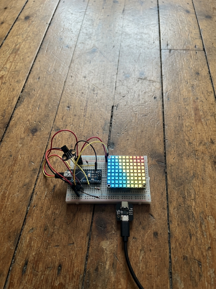
This project displays real-time temperature readings on a 16x8 RGB LED matrix that changes color based on how hot or cold it is. Built around an Arduino Uno, a temperature sensor, and addressable NeoPixel panels, it creates a visual thermometer that's both functional and eye-catching.
The guide includes a complete wiring diagram showing how to connect the LM35 temperature sensor and LED panels to the Arduino, a full parts list, and ready-to-upload firmware with customizable brightness settings. Assembly takes just a few minutes, and the code handles digit rendering and color mapping automatically.
Wiring diagram
Gather all the parts
Assemble it in 6 steps
1. Place the two LED panels
Put the two 8×8 RGB LED panels side by side with their arrows or labels showing data travelling from the first panel to the second. The panel nearest the Nano is matrix_1; use its DIN pin as the data input.
- Check the printed DIN and DOUT labels before wiring. Data must enter DIN and leave DOUT.
- Do not guess the power labels: connecting 5 V to GND can damage a panel immediately.
2. Connect power and ground
Connect supply_5v +5V to the 5V pin on matrix_1 and matrix_2 (power). Connect supply_5v GND to the GND pin on matrix_1, matrix_2, and a GND pin on the Nano (ground). Keep the Nano connected to its own USB cable for programming; do not connect the external 5 V supply to the Nano 5V pin.
- Use thicker, short wires for the 5 V and GND connections to the panels because LEDs draw more current than signal wires.
- All grounds must join together or the panels cannot understand the Nano’s data signal.
- Use a regulated 5 V supply rated for at least 4 A. A weak supply can cause flickering, resets, or hot wires.
3. Wire the panel data chain
Connect Nano digital pin D6 to one lead of the 330 Ω data_resistor (signal). Connect the resistor’s other lead to matrix_1 DIN (signal). Connect matrix_1 DOUT to matrix_2 DIN (signal).
- A resistor has no positive or negative direction, so either lead can face the Nano.
- Keep this data wire short and make sure it goes to DIN, not DOUT, on the first panel.
- Do not connect the Nano data wire directly to the second panel; the first panel’s DOUT must feed the second panel’s DIN.
4. Connect the temperature sensor
Connect lm35_1 VCC, normally the red wire, to the Nano 5V pin (power). Connect lm35_1 GND, normally the black wire, to Nano GND (ground). Connect lm35_1 SIG, normally the blue wire, to Nano A0 (signal).
- Keep the sensor away from the LED panels and their power supply, because their warmth can make it read high.
- A0 is the Nano pin marked A0, not digital pin 0.
- Make sure the sensor’s red and black wires are not swapped — swapped power can damage the temperature sensor.
5. Set brightness in the code
No brightness knob is used. In the sketch, find the line `const uint8_t BRIGHTNESS = 40;` and change 40 to the brightness you want before pressing Deploy. Use 0 for off and 255 for maximum brightness.
- Start at 40 for indoor use. A lower number uses less power and is easier on the eyes.
- The temperature colours and displayed number keep working at every brightness setting.
- Very high brightness can make the LED panels draw much more power, so keep using the separate regulated 5 V supply.
6. Check before powering up
With power unplugged, check that every panel has 5V and GND, the external supply ground joins Nano GND, and the only Nano data connection is D6 through the 330 Ω resistor to matrix_1 DIN. Then plug the Nano into USB and switch on the separate 5 V panel supply.
- The panels show the rounded temperature from 00 to 99. Blue means below 18°C, green 18–25°C, orange 26–30°C, and red 31°C or warmer.
- Never power the LED panels from the Nano’s 5V USB pin; 128 LEDs can overload the Nano’s USB connector and protection parts.
Review all connections
1. Connections between "supply_5v" and "Arduino"
2. Connections between "matrix_1" and "Arduino"
3. Connections between "matrix_2" and "Arduino"
4. Connections between "lm35_1" and "Arduino"
5. Connections between "data_resistor" and "Arduino"
Deploy the firmware
#include <Arduino.h>
#include <Adafruit_NeoPixel.h>
#include <math.h>


// Forward declarations
uint16_t pixelForXY(uint8_t x, uint8_t y);
void setXY(uint8_t x, uint8_t y, uint32_t color);
void drawDigit(uint8_t digit, uint8_t startX, uint32_t color);
uint32_t temperatureColor(float celsius);
void showTemperature(float celsius);

const uint8_t LED_DATA_PIN = 6;
const uint8_t TEMP_SENSOR_PIN = A0;
const uint16_t MATRIX_WIDTH = 16;
const uint16_t MATRIX_HEIGHT = 8;
const uint16_t PIXEL_COUNT = 128;
// Change this number whenever you want a different panel brightness:
// 0 = off, 255 = maximum. Start around 40 indoors.
const uint8_t BRIGHTNESS = 40;

Adafruit_NeoPixel pixels(PIXEL_COUNT, LED_DATA_PIN, NEO_GRB + NEO_KHZ800);

// Each 8x8 panel is assumed to be wired in horizontal zigzag rows.
uint16_t pixelForXY(uint8_t x, uint8_t y) {
  uint8_t panel = x / 8;
  uint8_t localX = x % 8;
  uint16_t localIndex = y * 8 + ((y & 1) ? (7 - localX) : localX);
  return panel * 64 + localIndex;
}

void setXY(uint8_t x, uint8_t y, uint32_t color) {
  if (x < MATRIX_WIDTH && y < MATRIX_HEIGHT) {
    pixels.setPixelColor(pixelForXY(x, y), color);
  }
}

const uint8_t digits[10][5] = {
  {7,5,5,5,7}, {2,6,2,2,7}, {7,1,7,4,7}, {7,1,7,1,7},
  {5,5,7,1,1}, {7,4,7,1,7}, {7,4,7,5,7}, {7,1,2,2,2},
  {7,5,7,5,7}, {7,5,7,1,7}
};

void drawDigit(uint8_t digit, uint8_t startX, uint32_t color) {
  for (uint8_t row = 0; row < 5; row++) {
    for (uint8_t col = 0; col < 3; col++) {
      if (digits[digit][row] & (1 << (2 - col))) {
        // Scale the 3x5 digit two times so it fills the 8-pixel-high panels.
        setXY(startX + col * 2, 1 + row, color);
        setXY(startX + col * 2 + 1, 1 + row, color);
      }
    }
  }
}

uint32_t temperatureColor(float celsius) {
  if (celsius < 18.0) return pixels.Color(0, 0, 180);      // blue: cool
  if (celsius < 26.0) return pixels.Color(0, 160, 0);      // green: comfortable
  if (celsius < 31.0) return pixels.Color(220, 80, 0);     // orange: warm
  return pixels.Color(220, 0, 0);                          // red: hot
}

void showTemperature(float celsius) {
  int displayTemp = (int)round(celsius);
  if (displayTemp < 0) displayTemp = 0;
  if (displayTemp > 99) displayTemp = 99;

  uint32_t color = temperatureColor(celsius);
  pixels.clear();
  drawDigit(displayTemp / 10, 0, color);
  drawDigit(displayTemp % 10, 8, color);
  pixels.show();
}

void setup() {
  analogReference(DEFAULT);
  pixels.begin();
  pixels.setBrightness(BRIGHTNESS);
  pixels.clear();
  pixels.show();
}

void loop() {
  int raw = analogRead(TEMP_SENSOR_PIN);
  float voltage = raw * (5.0 / 1023.0);
  float celsius = voltage * 100.0; // LM35: 10 mV for each degree C
  showTemperature(celsius);
  delay(500);
}
Remix this project
Make it yours in one click
Open a full copy of this project in your own Schematik workspace — diagram, code, parts, and assembly steps included. Swap the sensor, add features, or redesign the whole thing with AI. The author's original stays untouched.