Community project
The Exposed Connection Is 1/2-inch Bsp Recommend
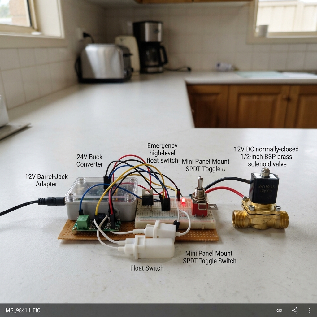
This project builds an autonomous water tank inlet controller using an ESP32 to manage a 12V solenoid valve with dual float-switch safety. The system monitors a main float to detect when the tank reaches its normal full level, while an emergency high-level float provides backup protection. The guide includes a complete wiring diagram, parts list, and firmware that implements debounced float sensing, opto-isolated safety monitoring, and fail-safe valve control logic.
Builders will receive step-by-step assembly instructions covering valve mounting, float placement, controller box installation, and the protected 12-volt valve circuit. The firmware excerpt demonstrates how the ESP32 reads float states, validates safety power availability, and drives the MOSFET gate to control the normally-closed solenoid. All safety states are tested before plumbing connection to ensure reliable autonomous operation.
Wiring diagram

Gather all the parts
Assemble it in 7 steps
1. Fit the water valve safely
Turn off the building water at the existing stop-cock, open a nearby tap to release pressure, then have a qualified plumber replace the exposed 1/2-inch BSP section with the 12 V normally-closed valve. Follow the flow arrow stamped on the valve body. Keep the valve itself in the wet plumbing area, but make every electrical join above splash level and inside a sealed junction box.
- The valve is closed when it has no electrical power, so this is the safe position while fitting it.
- Use thread sealant appropriate for potable-water plumbing.
- Do not work on a pressurized pipe; a loosened fitting can spray water and cause property damage.
- Do not install the ESP32, power adapter, or open wire joins in the bathroom splash zone.
2. Mount the two tank floats
Mount main_float at the normal full-water line and rotate or test it so its two wires connect together when water reaches that line. Mount backup_float a little higher and orient it so its two wires connect together below that emergency level, then separate when water rises to the emergency level. Run both low-voltage float cables back to the dry controller enclosure using protected cable.
- Before final mounting, use a multimeter to check each float while you move it by hand; float switch orientation changes whether its contact is open or closed.
- Leave enough cable slack to remove a float for cleaning.
- The backup float must open at high water; if it is reversed, it cannot remove power during an overflow.
- Keep float cables clear of the tank lid and any sharp edge that could cut their insulation.
3. Mount the dry controller box
Fit a sealed plastic enclosure in a dry, reachable place away from shower spray and outside the concealed-pipe wall. Mount the ESP32, the 12 V adapter connection, buck converter, fuse holder, MOSFET board parts, LED, and manual_off switch inside or on this enclosure. Bring the 12 V adapter lead into the enclosure through a strain-relief cable gland.
- Label the switch positions clearly: OPEN ENABLED for the position that connects COM to NO1, and OFF for the open position.
- Set the buck converter output to 5.0 V with a multimeter before connecting it to the ESP32 VIN pin.
- Do not put mains-voltage wiring inside the low-voltage enclosure unless a qualified electrician provides a properly rated separate compartment.
- A loose 12 V wire can heat up or damage parts; use screw terminals or crimped connectors, not twisted bare wire.
4. Build the protected 12-volt valve path
From power_adapter +12V, wire to valve_fuse IN, then valve_fuse OUT to manual_off COM. Wire manual_off NO1 to backup_float SAFETY_IN, and backup_float SAFETY_OUT to valve VALVE+. Wire valve VALVE- to mosfet Drain (D), and mosfet Source (S) to the common GND rail. Place flyback_diode across the valve: its striped CATHODE end goes to valve VALVE+, and its unstriped ANODE end goes to valve VALVE-.
- This chain means the switch OFF position or a high backup float removes 12 V from the valve even if the ESP32 is faulty.
- The diode goes directly across the valve wires, not in series with the valve.
- Do not reverse the flyback diode; reversed diode wiring can create a short circuit when the valve is powered.
- Use a fuse value only large enough for the valve's normal label current; do not bypass the fuse.
5. Wire the ESP32 control and indicator
Make one shared low-voltage GND rail: power_adapter GND, buck VIN-, buck VOUT-, ESP32 GND, and mosfet Source all join there. Wire buck VIN+ to power_adapter +12V, then buck VOUT+ to ESP32 VIN (power) and buck VOUT- to ESP32 GND (ground). Wire main_float GND to ESP32 GND (ground) and main_float SIGNAL to GPIO32 (level signal). Wire GPIO25 to gate_resistor A (control), gate_resistor B to mosfet Gate (control), and gate_pulldown from the MOSFET gate to GND (keeps the valve closed while the ESP32 starts). Wire GPIO26 to led_resistor A, led_resistor B to the LED long leg, and the LED short leg to GND (open-valve light).
- The LED's long leg is positive; it lights only when the ESP32 commands the valve open.
- The 10 kΩ resistor is important: it holds the MOSFET off during reset, so the valve stays closed until the ESP32 has read the tank level.
- Do not connect the 12 V valve wire to any ESP32 GPIO; ESP32 pins accept only 3.3 V logic signals and can be destroyed by 12 V.
- Make sure the LED has its 220 Ω resistor in series; connecting an LED directly to GPIO26 can damage the LED or board.
6. Connect the safety status monitor
Wire safety_sense IN+ to valve VALVE+ (the final switched 12 V at the valve), and safety_sense IN- to the common GND rail. Wire safety_sense VCC to ESP32 3V3 (power), safety_sense GND to ESP32 GND (ground), and safety_sense OUT to GPIO33 (status signal). This monitor lets the ESP32 see when the final valve supply is unavailable.
- With the manual switch OFF or the backup float high, the monitor reports that valve power is unavailable; this is expected.
- Use the input/output isolation arrangement printed on your exact opto module; terminals vary between module brands.
- Check the opto module really accepts a 12 V input and provides a 3.3 V-safe output before connecting it to GPIO33.
- Never share an unknown module output with 12 V; only its marked 3.3 V logic OUT terminal goes to the ESP32.
7. Test every safe state before plumbing use
With the valve plumbing complete and the tank floats accessible, plug in the 12 V adapter and press Deploy in Schematik. First set the manual_off switch to OFF: the valve must remain closed and the LED must be off. Then enable the switch with the main float in its low-water position: the LED should turn on and the valve should open. Lift the main float to its full position: the LED should turn off and the valve should close. Return the main float low, then lift the backup float: the valve must close even though the main float asks it to open. Finally, remove adapter power: the valve and LED must turn off and the valve must close.
- A faint click from the solenoid and the LED changing state are useful first checks before allowing water pressure through.
- Repeat the backup-float test periodically; it is the independent overflow protection.
- If any test produces the opposite result, unplug the 12 V adapter immediately and correct the float orientation or wiring before leaving the system connected.
- Do not rely on this system until both the normal-full and backup-high tests close the valve reliably.
Review all connections
1. Connections between "main_float" and "ESP32"
2. Connections between "backup_float" and "ESP32"
3. Connections between "valve" and "ESP32"
4. Connections between "mosfet" and "ESP32"
5. Connections between "power_adapter" and "ESP32"
6. Connections between "buck" and "ESP32"
7. Connections between "valve_led" and "ESP32"
8. Connections between "flyback_diode" and "ESP32"
9. Connections between "gate_resistor" and "ESP32"
10. Connections between "gate_pulldown" and "ESP32"
11. Connections between "safety_sense" and "ESP32"
12. Connections between "valve_fuse" and "ESP32"
13. Connections between "led_resistor" and "ESP32"
Deploy the firmware
#include <Arduino.h>
// Autonomous storage-tank inlet controller for ESP32 DevKit v1.
// GPIO25 drives the low-side MOSFET: HIGH energizes the normally-closed valve.
// The normal float is wired between GPIO32 and GND.  With INPUT_PULLUP,
// LOW means the tank has reached the normal full level.
// The isolated safety monitor is HIGH only while 12 V is present at VALVE+.


// Forward declarations
bool tankIsFullFromRawInput();
bool safetyPowerAvailable();
void applyValveState();

constexpr int VALVE_GATE_PIN = 25;
constexpr int VALVE_LED_PIN = 26;
constexpr int MAIN_FLOAT_PIN = 32;
constexpr int SAFETY_POWER_PIN = 33;

constexpr unsigned long DEBOUNCE_MS = 80;

bool rawMainFull = false;
bool stableMainFull = false;
unsigned long lastMainChangeMs = 0;

bool tankIsFullFromRawInput() {
  // Float contact closed to GND = water has reached the normal full line.
  return digitalRead(MAIN_FLOAT_PIN) == LOW;
}

bool safetyPowerAvailable() {
  // The opto module's stated logic is HIGH while its 12 V input is powered.
  // LOW means the manual cutoff is off, the backup float has opened, or
  // the 12 V safety chain is otherwise interrupted.
  return digitalRead(SAFETY_POWER_PIN) == HIGH;
}

void applyValveState() {
  const bool safetyOk = safetyPowerAvailable();
  const bool shouldOpenValve = !stableMainFull && safetyOk;

  // A LOW gate keeps the normally-closed valve de-energized and closed.
  digitalWrite(VALVE_GATE_PIN, shouldOpenValve ? HIGH : LOW);
  digitalWrite(VALVE_LED_PIN, shouldOpenValve ? HIGH : LOW);
}

void setup() {
  // Set outputs LOW before reading inputs, so reset/boot cannot command flow.
  pinMode(VALVE_GATE_PIN, OUTPUT);
  pinMode(VALVE_LED_PIN, OUTPUT);
  digitalWrite(VALVE_GATE_PIN, LOW);
  digitalWrite(VALVE_LED_PIN, LOW);

  pinMode(MAIN_FLOAT_PIN, INPUT_PULLUP);
  pinMode(SAFETY_POWER_PIN, INPUT_PULLUP);

  // Read the actual installed float position now; no float movement is needed
  // after a reboot or power restoration.
  rawMainFull = tankIsFullFromRawInput();
  stableMainFull = rawMainFull;
  lastMainChangeMs = millis();
  applyValveState();
}

void loop() {
  const unsigned long now = millis();
  const bool rawNow = tankIsFullFromRawInput();

  if (rawNow != rawMainFull) {
    rawMainFull = rawNow;
    lastMainChangeMs = now;
  }

  // Ignore brief contact chatter, but react to an already-present level at boot.
  if (rawMainFull != stableMainFull && now - lastMainChangeMs >= DEBOUNCE_MS) {
    stableMainFull = rawMainFull;
  }

  // The backup cut-off and manual switch are sampled every pass.  Even if the
  // ESP32 failed, their series 12 V path still removes coil power directly.
  applyValveState();
  delay(10);
}
Remix this project
Make it yours in one click
Open a full copy of this project in your own Schematik workspace — diagram, code, parts, and assembly steps included. Swap the sensor, add features, or redesign the whole thing with AI. The author's original stays untouched.