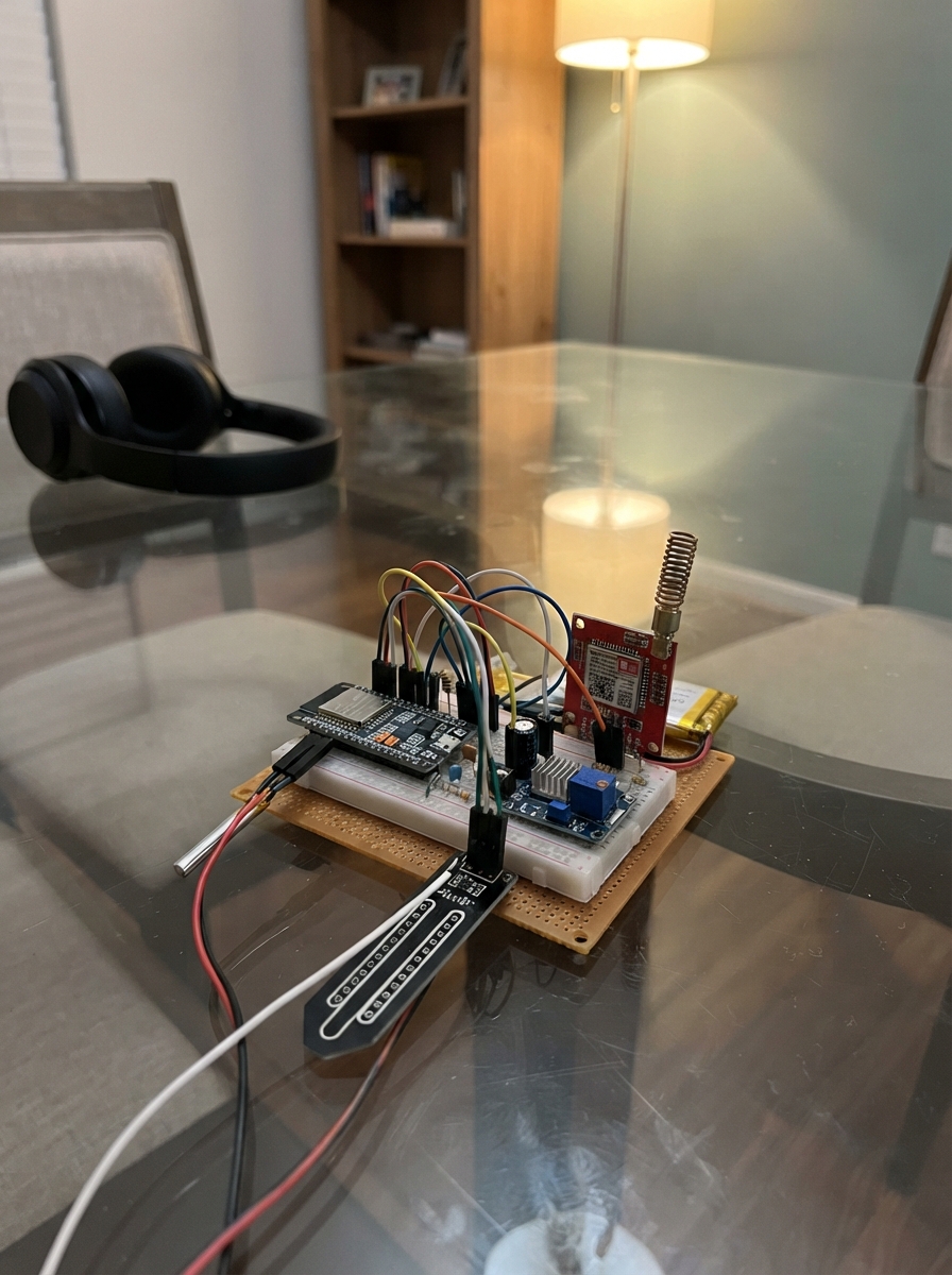
This project automates the aeration and mixing of a compost bin using an ESP32 microcontroller to monitor temperature and moisture while controlling a blower fan and mixing motor. The system tracks decomposition progress over time and can send status updates via GSM/GPRS, making it possible to manage compost from anywhere.
Built from readily available components including temperature and soil moisture sensors, 12V motors with a geared reducer and centrifugal blower, dual buck converters for power management, and a SIM800L module for remote communication, this guide provides a complete wiring diagram, parts list, firmware with calibration instructions, and step-by-step assembly to get a fully functional automated composter running.
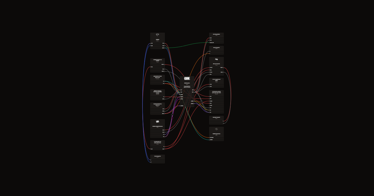
Wiring diagram
Gather all the parts
Assemble it in 8 steps
1. Keep the moving parts outside the breadboard
Use a 50 L vessel. Build the false floor, air manifold, blower, lid motor, shaft, bearing, and blades as before. Keep every moving part and all 12 V wires outside the dry electronics box; a solderless breadboard is only for the small controller wires.
- Leave at least 50 mm below the mesh for the air chamber.
- Test that the empty blade stack turns without touching the vessel.
- A breadboard must never carry blower or motor current; its thin metal clips can heat up, melt plastic, or start a fire.
2. Position the one breadboard
Use one full-size 830-tie-point breadboard. Straddle the ESP32 across the center groove with its USB socket facing an end. Use the left power rails as 3V3 and GND for the sensors. Place the SIM800L at the far end, then place the 4.7 kΩ, 10 kΩ, and 56 kΩ resistors plus the 100 nF capacitor in the remaining center rows. Keep the 2200 µF low-ESR capacitor beside the SIM800L but connect it directly to the GSM buck converter with short wires.
- Leave the right-side rails unused so the crowded signal wires stay easy to trace.
- The ESP32, SIM800L, resistors, and small capacitor fit on the breadboard; the probes connect with jumper leads from the vessel.
- Do not put either buck converter, the relay board, fuse, motor, or blower into breadboard holes; they are connected beside it with screw terminals and properly sized wire.
3. Wire the breadboard signal section
Connect DS18B20 VCC → ESP32 3V3 (power), GND → ESP32 GND (ground), and DATA → GPIO4 (temperature signal). Put the 4.7 kΩ resistor between the same GPIO4 row and 3V3. Connect moisture VCC → 3V3 (power), GND → GND (ground), and AOUT → GPIO33 (moisture signal); place the 100 nF capacitor from AOUT to GND. Connect SIM800L TX → GPIO16 (data). Connect GPIO17 through 10 kΩ to SIM800L RX, then connect 56 kΩ from SIM800L RX to GND; this makes the ESP32 signal safe for the GSM input.
- Use short jumpers for the SIM800L connections and keep its antenna outside the metal electronics box.
- All grounds, including both buck converters, ESP32, sensors, GSM module, and relay board, must join together.
- Never connect GPIO17 directly to SIM800L RX; the resistor pair prevents excessive voltage at that input.
4. Set and mount the two power converters
With the electronics disconnected, connect the 12 V adapter through the 5 A fuse. Set logic_buck to exactly 3.3 V for the relay board. Set gsm_buck to exactly 4.0 V for the SIM800L. Mount both converters on a non-conductive panel next to the breadboard and connect the 2200 µF low-ESR capacitor directly across the GSM converter output: + to VOUT+ and the striped - lead to VOUT-.
- Measure each output with a multimeter before attaching it to any module.
- Power the ESP32 from its USB socket while programming; do not feed the relay supply into its 3V3 pin.
- A converter set too high can permanently damage the SIM800L or relay board. Reversing the capacitor can make it burst.
5. Wire the relay board beside the breadboard
Mount the 3.3 V two-channel relay module beside, not on, the breadboard. Connect relay DC+ → the 3.3 V converter output (power), DC- → common GND (ground), IN1 → GPIO25 (blower control), and IN2 → GPIO26 (mixer control). Select high-level triggering on the relay board. Put the fused 12 V positive wire into both COM terminals. Connect NO1 → blower speed-controller positive input (switched blower power) and NO2 → mixer motor M+ (switched mixer power). Connect blower GND and motor M- directly to the 12 V return. Put the flyback diode across the motor: striped end to M+ and unstriped end to M-.
- Use screw terminals and wire rated for the motor's starting current.
- With the vessel empty, first test one relay channel at a time.
- Keep the bare 12 V screw terminals covered. A loose high-current wire can overheat, short the adapter, or start the motor unexpectedly.
6. Mount the dry controller box
Secure the breadboard, relay board, converters, fuse, and SIM800L in a dry box outside the compost vessel. Bring only the sensor cables and the motor/blower cables through strain-relieved holes. Plug the ESP32 into USB, connect the 12 V adapter, then use Deploy to load the controller.
- Firmware uses 10 minutes aeration every 3 hours, thermal ON at 60 C and release at 58 C, and 2 minutes mixing every 6 hours.
- Calibrate moisture endpoints in the actual substrate and set MOISTURE_CALIBRATED true before using 45 to 70 percent alerts.
- The five-day cool-temperature indicator resets after any power interruption and is not proof of maturity.
- Serial CSV is not persistent data logging; capture it externally throughout the trial.
- Validate motor starting and stall current for the larger vessel before loading; the existing motor and adapter are not certified adequate for 50 L.
- Label the 3.3 V relay supply, 4.0 V GSM supply, and 12 V motor wires so they cannot be mixed later.
- Insert an activated SIM card before powering the SIM800L.
- Unplug USB and the 12 V adapter before moving any jumper or screw-terminal wire; moisture near the controller can cause shorts and corrosion.
7. Add temperature supply decoupling
Place the additional 100 nF capacitor between DS18B20 VCC and GND close to the sensor connection. Retain the separate moisture signal filter.
- Keep the existing 3.3 V relay converter setting. This design still powers the ESP32 by USB; do not change that converter to 5 V with the current relay attached.
- Keep hands out of the vessel while powered. Relays and firmware are not emergency stops or independent overtemperature protection.
8. Add reset protection and capture uptime records
Connect each 10 kohm pulldown from its relay input to GND. Use high-trigger relays only. No RTC or microSD is used for this bench-testing build; GPIO21 and GPIO22 are unused.
- RECORD lines print over USB every five minutes and at actuator changes. They contain uptime and batch ID, not calendar time. Capture them externally if needed; no historical database is stored onboard.
- A restart preserves the batch identifier but resets schedules and the consecutive monitored-temperature period. Uptime wraps after about 49.7 days; use shorter bench runs and mark every reboot in external records.
- Test reset behavior with motor and blower disconnected. Pulldowns only suit the existing high-trigger configuration.
- Motor protection and supply ratings remain unverified for stall current. Do not run a loaded reactor until these are validated.
Review all connections
1. Connections between "temp_probe" and "ESP32"
2. Connections between "onewire_pullup" and "ESP32"
3. Connections between "moisture_probe" and "ESP32"
4. Connections between "moisture_filter" and "ESP32"
5. Connections between "gsm" and "ESP32"
6. Connections between "gsm_bulk_cap" and "ESP32"
7. Connections between "gsm_tx_divider_top" and "ESP32"
8. Connections between "gsm_tx_divider_bottom" and "ESP32"
9. Connections between "power_adapter" and "ESP32"
10. Connections between "logic_buck" and "ESP32"
11. Connections between "gsm_buck" and "ESP32"
12. Connections between "mixer_motor" and "ESP32"
13. Connections between "motor_flyback_diode" and "ESP32"
14. Connections between "blower" and "ESP32"
15. Connections between "dual_relay" and "ESP32"
16. Connections between "fuse" and "ESP32"
17. Connections between "temperature_decoupling" and "ESP32"
18. Connections between "fan_pulldown" and "ESP32"
19. Connections between "mixer_pulldown" and "ESP32"
Deploy the firmware
#define TINY_GSM_MODEM_SIM800
#include <Arduino.h>
#include <OneWire.h>
#include <DallasTemperature.h>
#include <TinyGsmClient.h>
#include <Preferences.h>
#include <freertos/FreeRTOS.h>
#include <freertos/queue.h>

constexpr int TEMP_PIN=4, MOISTURE_PIN=33, GSM_RX_PIN=16, GSM_TX_PIN=17;
constexpr int FAN_RELAY_PIN=25, MOTOR_RELAY_PIN=26;
constexpr bool RELAY_ACTIVE_LOW=false;
constexpr int RELAY_ON=RELAY_ACTIVE_LOW?LOW:HIGH, RELAY_OFF=RELAY_ACTIVE_LOW?HIGH:LOW;
// Placeholder endpoints: calibrate against this substrate before enabling alerts.
constexpr int MOISTURE_RAW_DRY=3000, MOISTURE_RAW_WET=1400;
constexpr bool MOISTURE_CALIBRATED=false;
constexpr uint32_t FAN_INTERVAL_MS=10800000UL, FAN_DURATION_MS=600000UL;
constexpr uint32_t MIX_INTERVAL_MS=21600000UL, MIX_DURATION_MS=120000UL;
constexpr uint32_t MATURITY_DURATION_MS=432000000UL;
Preferences batchPrefs;
uint32_t batchId=0;
void logRecord(const char *event);
OneWire wire(TEMP_PIN);
DallasTemperature temperatureSensors(&wire);
HardwareSerial SerialAT(2);
TinyGsm modem(SerialAT);
QueueHandle_t txQueue, commandQueue;
struct Sms { char text[161]; };
struct Command { bool newBatch; };
portMUX_TYPE statusMux=portMUX_INITIALIZER_UNLOCKED;
char sharedStatus[161]="Controller starting";
bool fanRunning=false,motorRunning=false,fanPulse=false,thermal=false;
bool tempValid=false,moistValid=false,maturityTiming=false,maturityReported=false;
bool conversionPending=false;
float coreTempC=NAN,rawTempC=NAN,moisturePercent=NAN;
int moistureRaw=0;
uint32_t lastFan=0,lastMix=0,fanStart=0,motorStart=0,lastSensor=0,conversionStart=0;
uint32_t maturityStart=0,lastAlert=0,lastCsv=0;
bool alertSent=false;
void setFan(bool on) {
 if(on==fanRunning)return;
 digitalWrite(FAN_RELAY_PIN,on?RELAY_ON:RELAY_OFF);fanRunning=on;
 Serial.printf("EVENT,%lu,fan,%s\n",millis(),on?"ON":"OFF");
 logRecord(on?"FAN_ON":"FAN_OFF");
}
void setMotor(bool on) {
 if(on==motorRunning)return;
 digitalWrite(MOTOR_RELAY_PIN,on?RELAY_ON:RELAY_OFF);motorRunning=on;
 Serial.printf("EVENT,%lu,mixer,%s\n",millis(),on?"ON":"OFF");
 logRecord(on?"MIXER_ON":"MIXER_OFF");
}
void notify(const String &s) {
 Sms m={};s.toCharArray(m.text,sizeof(m.text));
 if(xQueueSend(txQueue,&m,0)!=pdTRUE)Serial.println("SMS queue full; alert not queued");
 Serial.println(s);
}
// All modem operations belong to this task, never the actuator loop.
void gsmTask(void*) {
 Preferences prefs;prefs.begin("compost",false);
 String recipient=prefs.getString("phone","");
 SerialAT.begin(9600,SERIAL_8N1,GSM_RX_PIN,GSM_TX_PIN);
 vTaskDelay(pdMS_TO_TICKS(1000));
 bool ready=modem.restart() && modem.waitForNetwork(60000L);
 if(ready) {
  modem.sendAT("+CMGF=1");modem.waitResponse(3000L);
  modem.sendAT("+CNMI=2,2,0,0,0");modem.waitResponse(3000L);
 }
 uint32_t lastCheck=millis(),lastSmsAttempt=millis()-30000UL;
 String line,sender;bool body=false;
 for(;;) {
  if(millis()-lastCheck>=60000UL) {
   lastCheck=millis();
   if(!modem.testAT(1000L))modem.restart();
   ready=modem.waitForNetwork(10000L);
   if(ready) {
    modem.sendAT("+CMGF=1");modem.waitResponse(1000L);
    modem.sendAT("+CNMI=2,2,0,0,0");modem.waitResponse(1000L);
   }
   Serial.println(ready?"GSM registered":"GSM unavailable; retry in 60 s (automatic registration)");
  }
  while(SerialAT.available()) {
   char c=SerialAT.read();
   if(c=='\n') {
    line.trim();
    if(line.startsWith("+CMT:")) {
     int a=line.indexOf('"'),b=line.indexOf('"',a+1);
     sender=(a>=0&&b>a)?line.substring(a+1,b):"";body=true;
    } else if(body&&line.length()) {
     body=false;line.toUpperCase();
     // First phone pairs; existing owner alone may pair again or reset batch.
     if(line=="PAIR"&&sender.length()&&(!recipient.length()||recipient==sender)) {
      recipient=sender;prefs.putString("phone",recipient);
      modem.sendSMS(recipient,"Paired. Commands: STATUS, NEWBATCH.");
     } else if(sender==recipient&&recipient.length()) {
      if(line=="STATUS") {
       char snapshot[161];portENTER_CRITICAL(&statusMux);
       memcpy(snapshot,sharedStatus,sizeof(snapshot));portEXIT_CRITICAL(&statusMux);
       modem.sendSMS(recipient,String(snapshot));
      } else if(line=="NEWBATCH") {
       Command cmd={true};
       bool accepted=xQueueSend(commandQueue,&cmd,0)==pdTRUE;
       modem.sendSMS(recipient,accepted?"Batch reset queued.":"Reset queue full; try again.");
      }
     }
    }
    line="";
   } else if(c!='\r') {
    line+=c;if(line.length()>200){line="";body=false;}
   }
  }
  Sms m;
  if(ready&&recipient.length()&&millis()-lastSmsAttempt>=30000UL&&xQueuePeek(txQueue,&m,0)==pdTRUE) {
   lastSmsAttempt=millis();
   bool sent=modem.sendSMS(recipient,String(m.text));
   Serial.println(sent?"SMS accepted by modem (not delivery confirmation)":"SMS failed");
   if(sent)xQueueReceive(txQueue,&m,0);
  }
  vTaskDelay(pdMS_TO_TICKS(20));
 }
}
void readSensors(uint32_t now) {
 if(!conversionPending && now-lastSensor>=5000UL) {
  lastSensor=now;conversionStart=now;conversionPending=true;
  temperatureSensors.requestTemperatures();
 }
 if(!conversionPending || now-conversionStart<800UL)return;
 conversionPending=false;
 float t=temperatureSensors.getTempCByIndex(0);
 // Read only after a requested conversion has had 800 ms to finish.
 // 85 C is legitimate after conversion, not a permanent rejection value.
 rawTempC=t;
 tempValid=isfinite(t)&&t!=DEVICE_DISCONNECTED_C&&t>=-40&&t<=125;
 coreTempC=tempValid?t:NAN;
 moistureRaw=analogRead(MOISTURE_PIN);
 moistValid=moistureRaw>10&&moistureRaw<4085&&MOISTURE_RAW_DRY>MOISTURE_RAW_WET;
 moisturePercent=moistValid?constrain(100.0f*(MOISTURE_RAW_DRY-moistureRaw)/float(MOISTURE_RAW_DRY-MOISTURE_RAW_WET),0.0f,100.0f):NAN;
 Serial.printf("SAMPLE,%lu,%.2f,%d,%.1f,%d,%d\n",now,coreTempC,moistureRaw,moisturePercent,tempValid,moistValid);
}
// Uptime records only; capture externally for permanent storage.
void logRecord(const char *event) {
 const char *stamp="NO_RTC";
 char row[320]={};
 snprintf(row,sizeof(row),"%s,%lu,%lu,%s,%.2f,%d,%.1f,%d,%d,%d,%d,%d,%d,%d,%.2f",stamp,millis(),batchId,event,coreTempC,moistureRaw,moisturePercent,MOISTURE_CALIBRATED,tempValid,moistValid,fanRunning,motorRunning,thermal,maturityReported,rawTempC);
 Serial.print("RECORD,");Serial.println(row);
}
void setup() {
 Serial.begin(115200);
 // Preload OFF before enabling outputs; external pulldowns protect reset.
 digitalWrite(FAN_RELAY_PIN,RELAY_OFF);digitalWrite(MOTOR_RELAY_PIN,RELAY_OFF);
 pinMode(FAN_RELAY_PIN,OUTPUT);pinMode(MOTOR_RELAY_PIN,OUTPUT);
 analogReadResolution(12);analogSetPinAttenuation(MOISTURE_PIN,ADC_11db);
 temperatureSensors.begin();temperatureSensors.setWaitForConversion(false);
 Serial.println("Bench mode: uptime only; schedules reset at boot; no onboard history.");
 batchPrefs.begin("batch",false);batchId=batchPrefs.getUInt("id",1);
 logRecord("BOOT_OBSERVATION_RESET");
 txQueue=xQueueCreate(8,sizeof(Sms));commandQueue=xQueueCreate(2,sizeof(Command));
 if(!txQueue||!commandQueue){Serial.println("Queue allocation failure; outputs OFF");while(true)delay(1000);}
 if(xTaskCreate(gsmTask,"gsm",8192,nullptr,1,nullptr)!=pdPASS){Serial.println("GSM task failed; outputs OFF");while(true)delay(1000);}
 lastFan=lastMix=millis();lastSensor=millis()-5000UL;
 Serial.println("RECORD columns: clock_status,uptime_ms,batch,event,temp_C,moisture_raw,moisture_index,calibrated,temp_valid,moist_valid,fan,mixer,thermal,indicator,raw_temp_C");
 Serial.println("CSV: SAMPLE,uptime_ms,temp_C,moisture_raw,relative_percent,temp_valid,moist_valid");
}
void loop() {
 uint32_t now=millis();Command cmd;
 if(xQueueReceive(commandQueue,&cmd,0)==pdTRUE){
  setMotor(false);
  fanPulse=false;
  // Do not clear a thermal safety latch just because a new batch is requested.
  setFan(thermal);
  maturityTiming=false;maturityReported=false;maturityStart=0;
  lastFan=lastMix=now;alertSent=false;lastAlert=now;
  batchId++;batchPrefs.putUInt("id",batchId);logRecord("NEWBATCH");
 }
 readSensors(now);
 // Invalid temperature stops mixing and latches any existing thermal override.
 if(tempValid){if(coreTempC>=60)thermal=true;else if(coreTempC<=58)thermal=false;}
 if(motorRunning&&(thermal||!tempValid||now-motorStart>=MIX_DURATION_MS))setMotor(false);
 if(fanPulse&&now-fanStart>=FAN_DURATION_MS)fanPulse=false;
 if(!thermal&&!fanPulse&&!motorRunning&&now-lastFan>=FAN_INTERVAL_MS){fanPulse=true;fanStart=lastFan=now;}
 setFan(thermal||fanPulse);
 if(!motorRunning&&!fanRunning&&tempValid&&now-lastMix>=MIX_INTERVAL_MS){motorStart=lastMix=now;setMotor(true);}
 if(!tempValid||coreTempC>32){maturityTiming=false;} else {
  if(!maturityTiming){maturityTiming=true;maturityStart=now;}
  if(!maturityReported&&now-maturityStart>=MATURITY_DURATION_MS){maturityReported=true;notify("Temperature indicator: <=32 C for 5 monitored days. NOT proof of maturity; validate in laboratory.");}
 }
 bool bad=!tempValid||!moistValid||(tempValid&&coreTempC>65)||
   (MOISTURE_CALIBRATED&&moistValid&&(moisturePercent<45||moisturePercent>70));
 if(!bad)alertSent=false;
 if(bad&&(!alertSent||now-lastAlert>=43200000UL)) {
  notify("Reactor warning: check sensors, temperature >65 C, or calibrated moisture outside 45-70%. Send STATUS.");
  alertSent=true;lastAlert=now;
 }
 char stamp[24];snprintf(stamp,sizeof(stamp),"up=%lus",(unsigned long)(now/1000UL));
 char status[161]={};
 snprintf(status,sizeof(status),"B%lu %s T=%.1fC M=%.0f%%(%s) raw=%d fan=%d mix=%d thermal=%d 5day=%d",batchId,stamp,coreTempC,moisturePercent,MOISTURE_CALIBRATED?"relative":"UNCAL",moistureRaw,fanRunning,motorRunning,thermal,maturityReported);
 portENTER_CRITICAL(&statusMux);memcpy(sharedStatus,status,sizeof(status));portEXIT_CRITICAL(&statusMux);
 if(now-lastCsv>=300000UL){lastCsv=now;Serial.printf("LOG,%lu,%s\n",now,status);logRecord("SAMPLE_5MIN");}
 delay(10);
}
Remix this project
Make it yours in one click
Open a full copy of this project in your own Schematik workspace, diagram, code, parts, and assembly steps included. Swap the sensor, add features, or redesign the whole thing with AI. The author's original stays untouched.