Community project
Tiny Robot AI Assistant
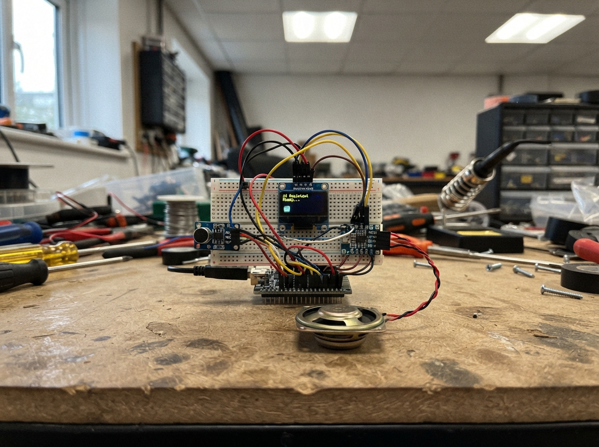
This project brings a tiny AI assistant to life on a Raspberry Pi Pico, complete with an expressive OLED face that responds to sound. The robot listens through a microphone amplifier, displays animated expressions on a 128×64 screen, and replies with audio through a small speaker powered by a Class-D amplifier.
The guide provides a complete wiring diagram, parts list, and step-by-step assembly instructions to connect the microphone input stage, speaker output stage, and display. Firmware is included to handle sound detection, facial animation, and audio playback, letting makers build an interactive desk companion that reacts to voice and sound in real time.
Wiring diagram

Gather all the parts
Assemble it in 5 steps
1. Keep the screen as the robot face
Leave the OLED where it is and check its four wires: VCC → Pico Mini 3V3 (power), GND → Pico Mini GND (ground), SDA → GP4 (data), and SCL → GP5 (timing).
- Keep the OLED pin labels visible while you add the other parts.
- Make sure VCC and GND are not swapped — swapped power can damage the screen.
2. Wire the microphone board
Connect MAX4466 VCC → Pico Mini 3V3 (power), MAX4466 GND → Pico Mini GND (ground), and MAX4466 OUT → Pico Mini GP26 (sound signal). Put the microphone opening on the outside of the robot case so your voice can reach it.
- Use short wires for OUT so electrical noise is less likely to trigger false replies.
- Start with the tiny gain screw near its middle position.
- Do not connect the microphone OUT wire to a 5V pin — GP26 accepts only the Pico Mini's 3.3V-level signal.
3. Wire the speaker amplifier
Connect PAM8302 VIN → Pico Mini 3V3 (power), PAM8302 GND → Pico Mini GND (ground), PAM8302 A+ → Pico Mini GP6 (audio signal), and PAM8302 A- → Pico Mini GND (audio reference). Leave the amplifier SD pin unconnected.
- Use red for VIN and black for every GND wire so you can inspect the power wiring easily.
- Do not connect the amplifier OUT+ or OUT- terminals to Pico Mini GND — they are two amplified speaker wires.
4. Connect the small speaker
Connect speaker POS → PAM8302 OUT+ (sound signal) and speaker NEG → PAM8302 OUT- (sound return). Mount the speaker with its front facing a hole or grille in the robot body so the sound can get out.
- Either speaker wire can be swapped for this single speaker; keep the two wires away from loose metal parts.
- Never connect the speaker directly to a Pico Mini pin — it needs the amplifier board.
5. Test the talking robot
With the USB cable unplugged, inspect every wire once more. Plug the Pico Mini into USB, speak close to the microphone or clap once, and the screen should show I HEAR YOU while the speaker plays a three-note robot reply.
- If it responds continuously, turn the microphone gain screw down a little.
- If it never responds, turn the microphone gain screw up a little and speak closer.
- Disconnect USB before moving any wire so a loose wire cannot touch the wrong pin.
Review all connections
1. Connections between "oled_1" and "Raspberry Pi Pico"
2. Connections between "mic_1" and "Raspberry Pi Pico"
3. Connections between "amp_1" and "Raspberry Pi Pico"
Deploy the firmware
#include <Arduino.h>
#include <Wire.h>
#include <Adafruit_GFX.h>
#include <Adafruit_SSD1306.h>


// Forward declarations
void drawEye(int centerX, bool happy);
void drawFace(const char *message, bool happy);
int readSoundLevel();
void playRobotReply();

constexpr int OLED_SDA_PIN = 4;
constexpr int OLED_SCL_PIN = 5;
constexpr int MIC_PIN = 26;
constexpr int SPEAKER_PIN = 6;
constexpr uint8_t SCREEN_WIDTH = 128;
constexpr uint8_t SCREEN_HEIGHT = 64;
constexpr uint8_t OLED_ADDRESS = 0x3C;
constexpr unsigned long SAMPLE_WINDOW_MS = 45;
constexpr unsigned long REPLY_COOLDOWN_MS = 1800;
constexpr int SOUND_THRESHOLD = 115;

Adafruit_SSD1306 display(SCREEN_WIDTH, SCREEN_HEIGHT, &Wire, -1);
unsigned long lastReplyAt = 0;

void drawEye(int centerX, bool happy) {
  display.fillRoundRect(centerX - 11, 18, 22, 21, 8, SSD1306_WHITE);
  display.fillCircle(centerX, happy ? 27 : 29, 5, SSD1306_BLACK);
  display.fillCircle(centerX + 2, happy ? 25 : 27, 2, SSD1306_WHITE);
}

void drawFace(const char *message, bool happy) {
  display.clearDisplay();
  display.drawRoundRect(1, 1, 126, 62, 9, SSD1306_WHITE);
  display.fillRoundRect(51, 4, 26, 4, 2, SSD1306_WHITE);
  drawEye(35, happy);
  drawEye(93, happy);
  if (happy) {
    display.drawLine(53, 46, 75, 46, SSD1306_WHITE);
    display.drawPixel(52, 45, SSD1306_WHITE);
    display.drawPixel(76, 45, SSD1306_WHITE);
  } else {
    display.drawLine(54, 48, 74, 48, SSD1306_WHITE);
  }
  display.setTextColor(SSD1306_WHITE);
  display.setTextSize(1);
  const int16_t textX = (128 - strlen(message) * 6) / 2;
  display.setCursor(textX, 53);
  display.print(message);
  display.display();
}

int readSoundLevel() {
  int lowValue = 1023;
  int highValue = 0;
  const unsigned long started = millis();
  while (millis() - started < SAMPLE_WINDOW_MS) {
    const int value = analogRead(MIC_PIN);
    if (value < lowValue) lowValue = value;
    if (value > highValue) highValue = value;
  }
  return highValue - lowValue;
}

void playRobotReply() {
  tone(SPEAKER_PIN, 660, 120);
  delay(145);
  tone(SPEAKER_PIN, 880, 160);
  delay(185);
  tone(SPEAKER_PIN, 1047, 220);
  delay(245);
  noTone(SPEAKER_PIN);
}

void setup() {
  pinMode(MIC_PIN, INPUT);
  pinMode(SPEAKER_PIN, OUTPUT);
  analogReadResolution(10);
Wire.begin();

  if (!display.begin(SSD1306_SWITCHCAPVCC, OLED_ADDRESS)) {
    for (;;) delay(1000);
  }
  drawFace("SAY HELLO", false);
}

void loop() {
  const int soundLevel = readSoundLevel();
  const unsigned long now = millis();
  if (soundLevel >= SOUND_THRESHOLD && now - lastReplyAt >= REPLY_COOLDOWN_MS) {
    lastReplyAt = now;
    drawFace("I HEAR YOU", true);
    playRobotReply();
    drawFace("SAY HELLO", false);
  }
}
Remix this project
Make it yours in one click
Open a full copy of this project in your own Schematik workspace — diagram, code, parts, and assembly steps included. Swap the sensor, add features, or redesign the whole thing with AI. The author's original stays untouched.
Related projects
Fridge Scale Smart Clip
Raspberry Pi Pico · September 14, 2026Phillip Knopp
Tiny Spider Robot
Raspberry Pi Pico · September 13, 2026Shaikh Tajmul haque
Portable ESP32 Laptop
Raspberry Pi Pico · September 12, 2026Sven Celikovic