Community project
Tiny Spider Robot
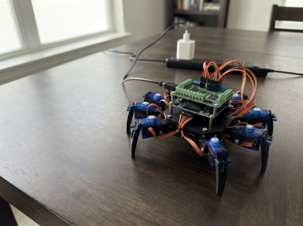
This eight-legged robot walks using a tripod gait, with each leg controlled by two servos for hip and knee movement. Built around a Raspberry Pi Pico, two PCA9685 PWM servo drivers, and eight SG90 servos, the spider can be assembled from laser-cut or 3D-printed parts and powered by a standard USB-C 5V adapter.
This guide provides a complete wiring diagram, parts list, and step-by-step assembly instructions. The included firmware handles servo calibration, gait sequencing, and coordinated leg movement. Builders will learn how to chain multiple servo drivers via I2C, mechanically center servo horns, and program smooth walking patterns on a microcontroller platform.
Wiring diagram

Gather all the parts
Assemble it in 5 steps
1. Make the spider body and legs
Make a light body plate from plastic, plywood, or a 3D-printed frame. Mount the 16 small servos in pairs: one hip servo and one knee servo for each of the four left and four right legs. Leave every servo horn loose for now so it can be fitted after the code centers the shaft.
- Keep the left and right legs as mirror images so the walking motion stays balanced.
- Use a body that is very light; SG90 servos are small and cannot safely lift a heavy frame.
- Do not force a servo shaft past its end stop — forcing it can strip the tiny plastic gears.
2. Connect the two servo driver boards
Place both PCA9685 driver boards near the center of the body. On each board connect VCC to the Pico Mini 3V3 pin (power), GND to Pico GND (ground), SDA to GP4 (data), and SCL to GP5 (clock). On the rear driver, bridge its A0 address pad or fit its address jumper so it uses address 0x41; leave the front driver at its normal 0x40 address.
- The SDA and SCL wires are shared: one Pico wire goes to the same-labelled pin on both driver boards.
- Use short wires for SDA and SCL to make the control connection reliable.
- Make sure VCC and GND are not swapped — swapped power can damage a driver board.
3. Add the strong 5 V servo power
With the 5 V adapter unplugged, connect its +5V output to the V+ terminal on both PCA9685 boards (power) and its GND output to the GND terminal on both boards (ground). The driver-board GND must also remain connected to Pico GND; this shared ground lets the Pico’s control signals work.
- Use thicker power wires for the 5 V and GND connections because 16 servos can pull several amps.
- A screw-terminal distribution block makes it easier to split the supply to both driver boards.
- Never feed the 5 V servo supply into the Pico 3V3 pin — that can permanently damage the Pico.
- Keep the 5 V adapter unplugged while changing servo wiring; a crossed power wire can overheat quickly.
4. Plug each leg servo into its numbered socket
Plug every servo into the three-pin outputs with the brown or black wire toward GND, the red wire toward V+, and the orange or yellow wire toward the signal pin. On the front driver use channels 0–7 for left legs: front hip 0, front knee 1, middle hip 2, middle knee 3, rear hip 4, rear knee 5, back hip 6, back knee 7. On the rear driver use the same channel numbers 0–7 for the matching right-leg joints.
- Label each servo cable before plugging it in; identical servo wires are easy to mix up.
- The first eight outputs on each board are the only ones used now; the remaining channels are spare.
- A backwards three-wire servo plug can damage the servo or driver board, so check that brown/black is on GND before applying power.
5. Center the joints and fit the horns
Put the body on a stand so all feet hang free. Plug the Pico Mini into USB, press Deploy in Schematik, then plug in the separate 5 V servo supply. The robot holds a centered standing pose for about two and a half seconds. During that time, fit each loose horn so the hip points sideways and each knee makes a stable bent leg. Unplug the 5 V supply before moving any horn again.
- Start with the feet wide and slightly below the body so the spider does not immediately tip over.
- If a joint moves the wrong direction, remove its horn while power is off and refit it one or more splines around.
- Keep fingers clear when the servo supply is connected — the legs can move suddenly when the program starts.
Review all connections
1. Connections between "servo_driver_front" and "Raspberry Pi Pico"
2. Connections between "servo_driver_rear" and "Raspberry Pi Pico"
3. Connections between "servo_supply" and "Raspberry Pi Pico"
4. Connections between "leg_left_front_hip" and "Raspberry Pi Pico"
5. Connections between "leg_left_front_knee" and "Raspberry Pi Pico"
6. Connections between "leg_left_middle_hip" and "Raspberry Pi Pico"
7. Connections between "leg_left_middle_knee" and "Raspberry Pi Pico"
8. Connections between "leg_left_rear_hip" and "Raspberry Pi Pico"
9. Connections between "leg_left_rear_knee" and "Raspberry Pi Pico"
10. Connections between "leg_left_back_hip" and "Raspberry Pi Pico"
11. Connections between "leg_left_back_knee" and "Raspberry Pi Pico"
12. Connections between "leg_right_front_hip" and "Raspberry Pi Pico"
13. Connections between "leg_right_front_knee" and "Raspberry Pi Pico"
14. Connections between "leg_right_middle_hip" and "Raspberry Pi Pico"
15. Connections between "leg_right_middle_knee" and "Raspberry Pi Pico"
16. Connections between "leg_right_rear_hip" and "Raspberry Pi Pico"
17. Connections between "leg_right_rear_knee" and "Raspberry Pi Pico"
18. Connections between "leg_right_back_hip" and "Raspberry Pi Pico"
19. Connections between "leg_right_back_knee" and "Raspberry Pi Pico"
Deploy the firmware
#include <Arduino.h>
#include <Wire.h>
#include <Adafruit_PWMServoDriver.h>

// Pico Mini I2C wiring.

// Forward declarations
uint16_t angleToTicks(int angle);
void setServo(Adafruit_PWMServoDriver &driver, uint8_t channel, int angle);
void setLeg(uint8_t leg, int hipAngle, int kneeAngle);
void standPose();
bool isTripodA(uint8_t leg);
void applyGaitPhase(uint8_t phase);

constexpr uint8_t I2C_SDA_PIN = 4;
constexpr uint8_t I2C_SCL_PIN = 5;

// PCA9685 servo timing at 50 Hz. Adjust only after mechanically centering horns.
constexpr uint16_t SERVO_MIN_US = 500;
constexpr uint16_t SERVO_MAX_US = 2500;
constexpr uint8_t SERVO_COUNT = 16;
constexpr uint8_t LEG_COUNT = 8;
constexpr unsigned long GAIT_STEP_MS = 280;

Adafruit_PWMServoDriver leftDriver(0x40);
Adafruit_PWMServoDriver rightDriver(0x41);

// Each leg has a hip joint and a knee joint. Channels 0-7 are left legs,
// front to back; channels 0-7 on the other board are the matching right legs.
const uint8_t leftHip[4]  = {0, 2, 4, 6};
const uint8_t leftKnee[4] = {1, 3, 5, 7};
const uint8_t rightHip[4]  = {0, 2, 4, 6};
const uint8_t rightKnee[4] = {1, 3, 5, 7};

// These neutral positions keep the supplied design conservative. The physical
// horn position can be adjusted while the robot is in this pose.
const int HIP_CENTER = 90;
const int KNEE_STAND = 112;
const int HIP_FORWARD = 72;
const int HIP_BACK = 108;
const int KNEE_LIFT = 82;

unsigned long lastStepTime = 0;
uint8_t gaitPhase = 0;

uint16_t angleToTicks(int angle) {
  angle = constrain(angle, 0, 180);
  const long pulseUs = map(angle, 0, 180, SERVO_MIN_US, SERVO_MAX_US);
  return (uint16_t)((pulseUs * 4096L) / 20000L);
}

void setServo(Adafruit_PWMServoDriver &driver, uint8_t channel, int angle) {
  driver.setPWM(channel, 0, angleToTicks(angle));
}

void setLeg(uint8_t leg, int hipAngle, int kneeAngle) {
  if (leg < 4) {
    setServo(leftDriver, leftHip[leg], hipAngle);
    setServo(leftDriver, leftKnee[leg], kneeAngle);
  } else {
    uint8_t rightLeg = leg - 4;
    setServo(rightDriver, rightHip[rightLeg], hipAngle);
    setServo(rightDriver, rightKnee[rightLeg], kneeAngle);
  }
}

void standPose() {
  for (uint8_t leg = 0; leg < LEG_COUNT; leg++) {
    setLeg(leg, HIP_CENTER, KNEE_STAND);
  }
}

bool isTripodA(uint8_t leg) {
  // Front-left, rear-left, middle-right, back-right.
  return leg == 0 || leg == 2 || leg == 5 || leg == 7;
}

void applyGaitPhase(uint8_t phase) {
  bool tripodAMoves = (phase == 0 || phase == 1);
  bool lifting = (phase == 0 || phase == 2);

  for (uint8_t leg = 0; leg < LEG_COUNT; leg++) {
    bool moving = isTripodA(leg) == tripodAMoves;
    int hip = HIP_CENTER;
    int knee = KNEE_STAND;

    if (moving) {
      hip = lifting ? HIP_FORWARD : HIP_BACK;
      knee = lifting ? KNEE_LIFT : KNEE_STAND;
    } else {
      hip = lifting ? HIP_BACK : HIP_FORWARD;
    }
    setLeg(leg, hip, knee);
  }
}

void setup() {
Wire.begin();

  leftDriver.begin();
  rightDriver.begin();
  leftDriver.setPWMFreq(50);
  rightDriver.setPWMFreq(50);

  // Center every servo first. Attach horns after this pose is reached.
  standPose();
  delay(2500);
  lastStepTime = millis();
}

void loop() {
  unsigned long now = millis();
  if (now - lastStepTime >= GAIT_STEP_MS) {
    lastStepTime = now;
    applyGaitPhase(gaitPhase);
    gaitPhase = (gaitPhase + 1) % 4;
  }
}
Remix this project
Make it yours in one click
Open a full copy of this project in your own Schematik workspace — diagram, code, parts, and assembly steps included. Swap the sensor, add features, or redesign the whole thing with AI. The author's original stays untouched.
Related projects
Fridge Scale Smart Clip
Raspberry Pi Pico · September 14, 2026Phillip Knopp
Tiny Robot AI Assistant
Raspberry Pi Pico · September 13, 2026Shaikh Tajmul haque
Portable ESP32 Laptop
Raspberry Pi Pico · September 12, 2026Sven Celikovic