Community project
Ultrasonic Distance Display
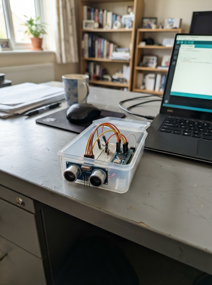
This project uses an ESP32 microcontroller and two HC-SR04 ultrasonic sensors to measure distances and publish readings over WiFi to an MQTT broker. It's ideal for parking space monitoring, object detection, or any application requiring dual-zone distance measurement with networked data reporting.
The guide provides a complete parts list, wiring diagram showing proper echo pin protection with resistors, step-by-step assembly instructions, and ready-to-deploy firmware. After connecting the sensors to the ESP32 and configuring WiFi and MQTT credentials, the system will continuously measure distances from both sensors and transmit the data to your network every two seconds.
Wiring diagram

Gather all the parts
Assemble it in 6 steps
1. Keep the USB-powered controller accessible
Use the Freenove ESP32-S3-WROOM CAM board powered by its own USB connection. Do not connect a separate supply to the board while USB is connected unless you have verified the board’s power arrangement.
- Keep the USB connector accessible for Schematik Deploy and normal power.
2. Wire the left HC-SR04 power connections
Connect sonar_left VCC to the board 5V rail and sonar_left GND to board GND.
- The sensor and ESP32 must share ground.
3. Wire the left trigger and protected echo input
Connect sonar_left TRIG to GPIO4. Make the ECHO divider: sonar_left ECHO to left_echo_top P1; join left_echo_top P2, left_echo_bottom P1, and GPIO1; connect left_echo_bottom P2 to GND.
- This 10 kΩ / 20 kΩ divider reduces the HC-SR04 5 V ECHO pulse to about 3.3 V.
- Never connect the HC-SR04 ECHO pin directly to ESP32 GPIO1.
4. Wire the right HC-SR04 power connections
Connect sonar_right VCC to the board 5V rail and sonar_right GND to board GND.
- Keep both sensor grounds tied to the same ESP32 ground.
5. Wire the right trigger and protected echo input
Connect sonar_right TRIG to GPIO5. Make the ECHO divider: sonar_right ECHO to right_echo_top P1; join right_echo_top P2, right_echo_bottom P1, and GPIO2; connect right_echo_bottom P2 to GND.
- Keep the two ultrasonic modules physically aimed at their respective zones.
- Never connect the HC-SR04 ECHO pin directly to ESP32 GPIO2.
6. Enter network settings and deploy
Before deploying, replace the clearly marked Wi-Fi and MQTT placeholders at the top of main.cpp. The firmware publishes retained readings every two seconds to <topic-prefix>/left/distance_cm and <topic-prefix>/right/distance_cm. A timeout is published as null.
- The default topic prefix is parking/zone.
- Use Schematik’s Deploy button after entering the actual connection details.
- The current MQTT connection is unencrypted port 1883 and intended for a trusted local network.
Review all connections
1. Connections between "sonar_left" and "ESP32"
2. Connections between "left_echo_bottom" and "ESP32"
3. Connections between "sonar_right" and "ESP32"
4. Connections between "right_echo_bottom" and "ESP32"
5. Connections between "left_echo_top" and "ESP32"
6. Connections between "right_echo_top" and "ESP32"
Deploy the firmware
#include <Arduino.h>
#include <WiFi.h>
#include <PubSubClient.h>

// Replace these placeholders before deploying to your network.

// Forward declarations
float readDistanceCm(int trigPin, int echoPin);
void connectWiFi();
void connectMqtt();
void publishDistance(const char *zone, float distanceCm);

const char *WIFI_SSID = "YOUR_WIFI_NAME";
const char *WIFI_PASSWORD = "YOUR_WIFI_PASSWORD";
const char *MQTT_HOST = "192.168.1.100";  // Replace with broker IP address or hostname.
constexpr uint16_t MQTT_PORT = 1883;
const char *TOPIC_PREFIX = "parking/zone";

constexpr int LEFT_TRIG_PIN = 4;
constexpr int LEFT_ECHO_PIN = 1;
constexpr int RIGHT_TRIG_PIN = 5;
constexpr int RIGHT_ECHO_PIN = 2;
constexpr unsigned long PUBLISH_INTERVAL_MS = 2000UL;
constexpr unsigned long ECHO_TIMEOUT_US = 30000UL;

WiFiClient wifiClient;
PubSubClient mqttClient(wifiClient);
unsigned long lastPublishMs = 0;

float readDistanceCm(int trigPin, int echoPin) {
  digitalWrite(trigPin, LOW);
  delayMicroseconds(3);
  digitalWrite(trigPin, HIGH);
  delayMicroseconds(10);
  digitalWrite(trigPin, LOW);

  const unsigned long durationUs = pulseIn(echoPin, HIGH, ECHO_TIMEOUT_US);
  if (durationUs == 0) return -1.0F;
  return (durationUs * 0.0343F) / 2.0F;
}

void connectWiFi() {
  if (WiFi.status() != WL_CONNECTED) {
    WiFi.mode(WIFI_STA);
    WiFi.begin(WIFI_SSID, WIFI_PASSWORD);
  }
}

void connectMqtt() {
  if (WiFi.status() != WL_CONNECTED || mqttClient.connected()) return;

  const String clientId = "parking-s3-" + String((uint32_t)(ESP.getEfuseMac() & 0xFFFFFFFF), HEX);
  mqttClient.connect(clientId.c_str());
}

void publishDistance(const char *zone, float distanceCm) {
  char topic[80];
  char payload[16];
  snprintf(topic, sizeof(topic), "%s/%s/distance_cm", TOPIC_PREFIX, zone);

  if (distanceCm < 0.0F) {
    snprintf(payload, sizeof(payload), "null");
  } else {
    snprintf(payload, sizeof(payload), "%.1f", distanceCm);
  }
  mqttClient.publish(topic, payload, true);
}

void setup() {
  Serial.begin(115200);
  pinMode(LEFT_TRIG_PIN, OUTPUT);
  pinMode(LEFT_ECHO_PIN, INPUT);
  pinMode(RIGHT_TRIG_PIN, OUTPUT);
  pinMode(RIGHT_ECHO_PIN, INPUT);
  digitalWrite(LEFT_TRIG_PIN, LOW);
  digitalWrite(RIGHT_TRIG_PIN, LOW);

  mqttClient.setServer(MQTT_HOST, MQTT_PORT);
  connectWiFi();
}

void loop() {
  connectWiFi();
  connectMqtt();
  mqttClient.loop();

  const unsigned long now = millis();
  if (mqttClient.connected() && now - lastPublishMs >= PUBLISH_INTERVAL_MS) {
    // Read sensors in sequence to reduce ultrasonic cross-talk.
    const float leftCm = readDistanceCm(LEFT_TRIG_PIN, LEFT_ECHO_PIN);
    delay(60);
    const float rightCm = readDistanceCm(RIGHT_TRIG_PIN, RIGHT_ECHO_PIN);

    publishDistance("left", leftCm);
    publishDistance("right", rightCm);
    lastPublishMs = now;
  }
}
Remix this project
Make it yours in one click
Open a full copy of this project in your own Schematik workspace — diagram, code, parts, and assembly steps included. Swap the sensor, add features, or redesign the whole thing with AI. The author's original stays untouched.