Community project
Um Projeto De Mini Gps Com Tela Redonda
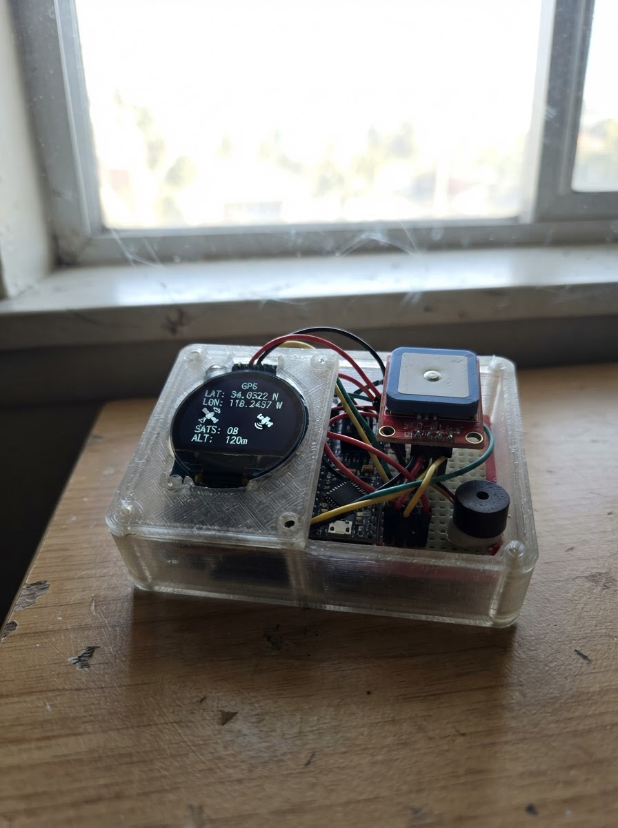
This project builds a portable GPS navigator with a round 1.28-inch display, perfect for tracking location and heading in real-time. The ESP32 microcontroller reads position data from a NEO-6M GPS module and renders an interactive map on the GC9A01 circular TFT screen, with audio alerts from the buzzer for proximity warnings.
The guide provides a complete wiring diagram showing how to connect the round display, GPS receiver, and buzzer to the ESP32, along with a full parts list and step-by-step assembly instructions. Firmware based on TinyGPS++ and Adafruit graphics libraries is included, featuring map rendering, heading display, and alert system integration via WiFi configuration.
Wiring diagram

Gather all the parts
Assemble it in 5 steps
1. Desligue tudo e prepare a alimentação USB
Com o ESP32 desconectado, posicione o ESP32 DevKit v1, a tela GC9A01, o NEO-6M e o buzzer. A alimentação continua sendo pela porta USB do ESP32.
- Use jumpers curtos para a tela SPI.
- Todos os módulos devem compartilhar o mesmo GND.
- Não conecte 5 V aos pinos de sinal do GPS ou da tela; o ESP32 usa sinais de 3,3 V.
2. Conecte a tela redonda
Ligue VCC e BL/BLK da tela a 3V3, e GND ao GND. Ligue SCK/CLK ao GPIO18, MOSI/DIN ao GPIO23, CS ao GPIO19, DC ao GPIO26 e RST ao GPIO25.
- MOSI pode estar marcado como DIN ou SDA; SCK pode estar marcado como CLK ou SCL.
- Confira a serigrafia do seu módulo antes de energizar.
- O pino SCL/CLK da GC9A01 é clock SPI e deve ir ao GPIO18, não ao GPIO22.
3. Conecte o receptor GPS
Ligue VCC do NEO-6M a 3V3 e GND ao GND. Ligue TX do GPS ao GPIO16 do ESP32 e RX do GPS ao GPIO17.
- A serial é cruzada: TX de um equipamento vai ao RX do outro.
- Para obter sinal inicial, deixe a antena cerâmica voltada para o céu em uma área aberta.
- Se o seu breakout especificar somente alimentação de 5 V, confirme a documentação do modelo antes de alterar esta ligação.
4. Conecte o buzzer
Ligue SIGNAL do buzzer ao GPIO4 e GND ao GND do ESP32.
- Use um buzzer piezo de 3,3 V.
- Não conecte um buzzer de alta potência diretamente ao GPIO; use um driver se ele exceder a corrente suportada pelo pino.
5. Use a ponte Wi-Fi do mapa
Após usar Deploy, conecte o ESP32 à rede Wi-Fi pelo portal MiniGPS-Setup. No telefone, abra o endereço IP do ESP32 na mesma rede. A página permite enviar latitude, longitude, direção e linhas de ruas; o dispositivo desenha as linhas em preto e branco e mantém a seta no centro.
- O formato das ruas é lat,lon|lat,lon para cada rua, separando ruas com ponto e vírgula.
- Uma automação ou aplicativo complementar do telefone pode enviar POST para /map com os campos lat, lon, heading e roads.
- O Google Maps não oferece a tela nem sua geometria de ruas diretamente ao ESP32. Esta ponte recebe dados que uma automação/app autorizado no telefone obtiver e simplificar.
- Use o mapa apenas como apoio visual e mantenha atenção total ao trânsito.
Review all connections
1. Connections between "display_1" and "ESP32"
2. Connections between "gps_1" and "ESP32"
3. Connections between "buzzer_1" and "ESP32"
Deploy the firmware
#include <Arduino.h>
#include <SPI.h>
#include <WiFi.h>
#include <WebServer.h>
#include <WiFiManager.h>
#include <TinyGPS++.h>
#include <Adafruit_GFX.h>
#include <Adafruit_GC9A01A.h>


// Hoisted type definitions
struct Geo { double lat,lon; };

struct Road { Geo p[MAX_POINTS]; uint8_t n; };

struct Alert { double lat,lon; uint16_t radius; const char *label; };


// Forward declarations
bool parsePoint(String s,Geo &p);
void parseRoads(String data);
void project(Geo p,int &x,int &y);
void arrow(float h);
void drawMap();
const Alert* nearest(const Alert *points,size_t n,double &d);
void alerts();
String page();
void receiveMap();

constexpr int TFT_SCK=18,TFT_MOSI=23,TFT_CS=19,TFT_DC=26,TFT_RST=25;
constexpr int GPS_RX_PIN=16,GPS_TX_PIN=17,BUZZER_PIN=4;
constexpr uint16_t BLACK=0x0000,WHITE=0xFFFF,GRAY=0x8410,DARK_GRAY=0x4208;
constexpr uint8_t MAX_ROADS=16,MAX_POINTS=12;


const Alert radars[1]={{0,0,0,"RADAR"}}, dangers[1]={{0,0,0,"PERIGO"}};
constexpr size_t RADAR_COUNT=0,DANGER_COUNT=0;
Adafruit_GC9A01A tft(TFT_CS,TFT_DC,TFT_RST);
TinyGPSPlus gps; HardwareSerial gpsSerial(2); WebServer server(80);
Road roads[MAX_ROADS]; uint8_t roadCount=0;
double mapLat=0,mapLon=0; float mapHeading=0; bool phoneMap=false,redraw=true,alarmOn=false; uint32_t lastDraw=0;

bool parsePoint(String s,Geo &p){int c=s.indexOf(',');if(c<1)return false;double a=s.substring(0,c).toDouble(),b=s.substring(c+1).toDouble();if(a < -90 || a > 90 || b < -180 || b > 180)return false;p={a,b};return true;}
void parseRoads(String data){roadCount=0;int start=0;while(start<data.length()&&roadCount<MAX_ROADS){int end=data.indexOf(';',start);if(end<0)end=data.length();String line=data.substring(start,end);roads[roadCount].n=0;int ps=0;while(ps<line.length()&&roads[roadCount].n<MAX_POINTS){int pe=line.indexOf('|',ps);if(pe<0)pe=line.length();Geo p;if(parsePoint(line.substring(ps,pe),p))roads[roadCount].p[roads[roadCount].n++]=p;ps=pe+1;}if(roads[roadCount].n>=2)roadCount++;start=end+1;}}
void project(Geo p,int &x,int &y){double north=(p.lat-mapLat)*111320.0,east=(p.lon-mapLon)*111320.0*cos(mapLat*DEG_TO_RAD);x=120+(int)(east*.75);y=120-(int)(north*.75);}
void arrow(float h){float a=(h-90)*DEG_TO_RAD;int x1=120+(int)(15*cosf(a)),y1=120+(int)(15*sinf(a));int x2=120+(int)(-10*cosf(a)-8*sinf(a)),y2=120+(int)(-10*sinf(a)+8*cosf(a));int x3=120+(int)(-10*cosf(a)+8*sinf(a)),y3=120+(int)(-10*sinf(a)-8*cosf(a));tft.fillTriangle(x1,y1,x2,y2,x3,y3,WHITE);tft.drawTriangle(x1,y1,x2,y2,x3,y3,BLACK);}
void drawMap(){tft.fillScreen(BLACK);tft.drawCircle(120,120,116,WHITE);tft.drawCircle(120,120,115,WHITE);tft.setTextColor(WHITE);tft.setTextSize(1);tft.setCursor(116,9);tft.print("N");if(!phoneMap&&!gps.location.isValid()){tft.setCursor(44,116);tft.print("AGUARDANDO GPS");return;}for(uint8_t r=0;r<roadCount;r++)for(uint8_t i=1;i<roads[r].n;i++){int x1,y1,x2,y2;project(roads[r].p[i-1],x1,y1);project(roads[r].p[i],x2,y2);tft.drawLine(x1,y1,x2,y2,WHITE);tft.drawLine(x1+1,y1,x2+1,y2,DARK_GRAY);}tft.drawCircle(120,120,18,GRAY);tft.fillCircle(120,120,16,BLACK);arrow(mapHeading);tft.setCursor(8,225);tft.print(phoneMap?"MAPA DO TELEFONE":"GPS LOCAL");}
const Alert* nearest(const Alert *points,size_t n,double &d){const Alert *best=nullptr;d=1e9;for(size_t i=0;i<n;i++){double v=TinyGPSPlus::distanceBetween(mapLat,mapLon,points[i].lat,points[i].lon);if(v<d){d=v;best=&points[i];}}return best;}
void alerts(){if(!phoneMap&&!gps.location.isValid())return;double a,b;const Alert *p=nearest(dangers,DANGER_COUNT,a);if(!(p&&a<=p->radius))p=nearest(radars,RADAR_COUNT,b);bool warn=p&&((p==&dangers[0]&&a<=p->radius)||(p!=&dangers[0]&&b<=p->radius));if(warn!=alarmOn){ledcWriteTone(BUZZER_PIN,warn?2200:0);alarmOn=warn;}}
String page(){return R"HTML(<!doctype html><meta name="viewport" content="width=device-width,initial-scale=1"><body style="font-family:Arial;max-width:600px;margin:auto;padding:16px"><h2>Mini GPS - ponte de mapa</h2><p>O Google Maps nao entrega diretamente sua tela ou ruas ao ESP32. Envie a posicao, direcao e linhas de ruas de uma automacao/app do telefone para este mapa minimalista.</p><p>Formato de ruas: <code>lat,lon|lat,lon</code>; separe ruas por <code>;</code>.</p><form method="post" action="/map">Latitude <input name="lat" required><br>Longitude <input name="lon" required><br>Direcao (0=N, 90=L) <input name="heading" value="0"><br>Ruas <textarea name="roads" rows="6" style="width:100%"></textarea><br><button>Enviar mapa</button></form><p>API: POST /map com lat, lon, heading e roads. Telefone e dispositivo devem estar no mesmo Wi-Fi.</p></body>)HTML";}
void receiveMap(){if(!server.hasArg("lat")||!server.hasArg("lon")){server.send(400,"text/plain","Envie lat e lon.");return;}Geo p;if(!parsePoint(server.arg("lat")+","+server.arg("lon"),p)){server.send(400,"text/plain","Coordenadas invalidas.");return;}float h=server.hasArg("heading")?server.arg("heading").toFloat():0;if(h<0||h>=360){server.send(400,"text/plain","Direcao entre 0 e 359.");return;}mapLat=p.lat;mapLon=p.lon;mapHeading=h;if(server.hasArg("roads"))parseRoads(server.arg("roads"));phoneMap=true;redraw=true;server.send(200,"application/json","{\"ok\":true,\"roads\":"+String(roadCount)+"}");}
void setup(){Serial.begin(115200);ledcAttach(BUZZER_PIN,2000,8);ledcWriteTone(BUZZER_PIN,0);SPI.begin(TFT_SCK,-1,TFT_MOSI,TFT_CS);tft.begin();tft.setRotation(0);gpsSerial.begin(9600,SERIAL_8N1,GPS_RX_PIN,GPS_TX_PIN);WiFiManager wm;wm.setConfigPortalTimeout(180);wm.autoConnect("MiniGPS-Setup");server.on("/",HTTP_GET,[](){server.send(200,"text/html",page());});server.on("/map",HTTP_POST,receiveMap);server.on("/status",HTTP_GET,[](){server.send(200,"application/json","{\"ip\":\""+WiFi.localIP().toString()+"\",\"mapActive\":"+String(phoneMap?"true":"false")+"}");});server.begin();}
void loop(){while(gpsSerial.available())gps.encode(gpsSerial.read());server.handleClient();uint32_t now=millis();if(!phoneMap&&gps.location.isValid()){double a=gps.location.lat(),b=gps.location.lng();float h=gps.course.isValid()?gps.course.deg():mapHeading;if(fabs(a-mapLat)>.00001||fabs(b-mapLon)>.00001||fabs(h-mapHeading)>3){mapLat=a;mapLon=b;mapHeading=h;redraw=true;}}if(redraw&&now-lastDraw>=50){lastDraw=now;redraw=false;drawMap();}alerts();}
Remix this project
Make it yours in one click
Open a full copy of this project in your own Schematik workspace — diagram, code, parts, and assembly steps included. Swap the sensor, add features, or redesign the whole thing with AI. The author's original stays untouched.
Related projects

Create A Complete Electrical Schematic Esp32 Sma
ESP32 · September 17, 2026Ayansh Agrawal
ESP32 Kare Ekran Projeleri
ESP32 · September 16, 2026Seref Ai
Component Qty --------------------------- ------
ESP32 · September 16, 2026Yathartha Chakrawal