Community project
Underwater ROV Thruster Controller
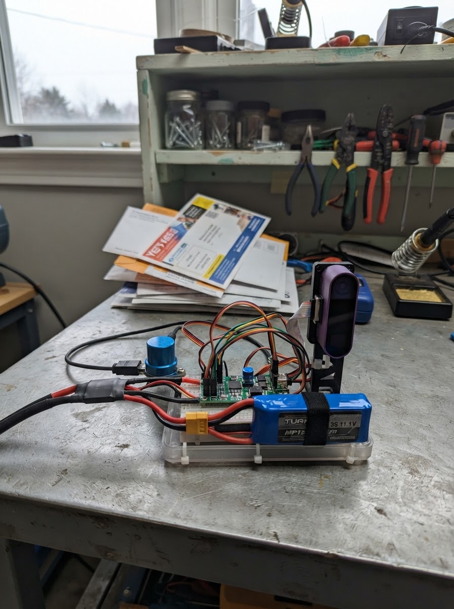
This guide builds a three-axis underwater ROV thruster controller powered by an ESP32 microcontroller. The system combines vectored thrust control via three 30A ESCs, real-time depth and distance sensing from a Ping sonar module, and AI-powered object detection through a HuskyLens camera—all coordinated through a single command interface.
Readers will receive a complete wiring diagram showing power distribution from the 3S LiPo battery through the buck converter to logic and thruster circuits, a full parts list with watertight housing specifications, Arduino firmware with UART communication handlers for both sonar and camera sensors, and step-by-step assembly instructions including electrical checkout and pressure testing procedures.
Wiring diagram

Gather all the parts
Assemble it in 6 steps
1. Disconnect propulsion power
Remove the 3S battery connection and keep all propellers removed while adding the camera wiring.
- This prevents an accidental motor start while working on the electronics.
- Do not work on the wiring with the propulsion battery connected.
2. Mount the AI camera in a watertight optical housing
Secure huskylens_camera behind a flat, clear optical window in the ROV enclosure. Keep the window clean, scratch-free, and close to the lens; point the camera forward and avoid trapping air bubbles in front of it.
- A flat window is preferable to a curved dome for a simple forward-looking setup.
- Use a pressure-rated enclosure and cable gland appropriate for the intended depth.
- HuskyLens itself is not waterproof. Water ingress will damage it.
- Object recognition is affected by underwater turbidity, colour loss, reflections, and low light; add external ROV lighting if necessary.
3. Power the camera from the regulated 5 V logic rail
Connect huskylens_camera VCC to the 5 V VOUT of logic_buck and connect huskylens_camera GND to the common logic ground. The buck regulator must have sufficient spare output current for the ESP32, sonar, and camera.
- Use short power leads and a solid common-ground connection.
- The existing 5 V / 3 A regulator is adequate for this low-power camera alongside the controller electronics when correctly wired.
- Never connect the 3S battery directly to the camera.
4. Connect the UART data pair
Cross the UART wires: connect huskylens_camera TX to ESP32 GPIO32 and huskylens_camera RX to ESP32 GPIO33. Leave the existing Ping sonar on GPIO16 and GPIO17 unchanged.
- Keep the TX/RX data leads away from high-current ESC and thruster power wires.
- Use twisted pairs or shielded cable for long internal runs in a noisy ROV enclosure.
- A shared ground is required for UART communication.
- Do not swap the camera and sonar UART pins.
5. Set the camera’s local recognition mode
Before closing the enclosure, power the 5 V logic rail and use the HuskyLens built-in screen and controls to select Object Recognition mode. Teach each desired target; the camera assigns it an object ID.
- Train using targets under lighting and water conditions similar to the actual mission.
- The firmware sends each detected target as OBJECT id,x,y,width,height over USB serial.
- Do not rely on camera detection alone for navigation, collision avoidance, or safety-critical control.
6. Complete the ROV electrical and watertightness check
Verify the three ESC signal connections, Ping sonar wiring, camera wiring, and every common ground before reconnecting the 3S battery. Perform a dry electronics check with propellers removed, then pressure/leak-test the sealed enclosure before water use.
- Use the firmware STATUS command to see CAMERA=READY or CAMERA=OFFLINE.
- Use the Deploy button in Schematik to compile and flash the controller.
- Fit the existing propulsion fuse/disconnect as specified in the ROV build.
- Never place hands near installed propellers while the battery is connected.
Review all connections
1. Connections between "esc_left" and "ESP32"
2. Connections between "esc_right" and "ESP32"
3. Connections between "esc_vertical" and "ESP32"
4. Connections between "logic_buck" and "ESP32"
5. Connections between "ping_sonar" and "ESP32"
6. Connections between "huskylens_camera" and "ESP32"
Deploy the firmware
#include <Arduino.h>
#include <ESP32Servo.h>
#include <HUSKYLENS.h>


// Forward declarations
int throttleToPulse(int throttle);
void writeThrusters(int left, int right, int vertical);
void stopThrusters();
void printHelp();
void processCommand(String line);
void readConsole();
void forwardSonarFrames();
void reportCameraObjects();

constexpr int ESC_LEFT_PIN = 25;
constexpr int ESC_RIGHT_PIN = 26;
constexpr int ESC_VERTICAL_PIN = 27;
constexpr int SONAR_RX_PIN = 16;
constexpr int SONAR_TX_PIN = 17;
constexpr int CAMERA_RX_PIN = 32;
constexpr int CAMERA_TX_PIN = 33;
constexpr int PWM_NEUTRAL_US = 1500;
constexpr int PWM_MIN_US = 1100;
constexpr int PWM_MAX_US = 1900;
constexpr uint32_t COMMAND_TIMEOUT_MS = 500;
constexpr uint32_t STATUS_INTERVAL_MS = 250;
constexpr uint32_t CAMERA_POLL_INTERVAL_MS = 100;

Servo leftEsc;
Servo rightEsc;
Servo verticalEsc;
HardwareSerial sonarSerial(2);
HardwareSerial cameraSerial(1);
HUSKYLENS huskylens;
int leftCommand = 0;
int rightCommand = 0;
int verticalCommand = 0;
bool cameraReady = false;
uint32_t lastCommandMs = 0;
uint32_t lastStatusMs = 0;
uint32_t lastCameraPollMs = 0;
String commandLine;

int throttleToPulse(int throttle) { return map(constrain(throttle, -100, 100), -100, 100, PWM_MIN_US, PWM_MAX_US); }
void writeThrusters(int left, int right, int vertical) { leftEsc.writeMicroseconds(throttleToPulse(left)); rightEsc.writeMicroseconds(throttleToPulse(right)); verticalEsc.writeMicroseconds(throttleToPulse(vertical)); }
void stopThrusters() { leftCommand = 0; rightCommand = 0; verticalCommand = 0; writeThrusters(0, 0, 0); }

void printHelp() {
  Serial.println("Commands: T left right vertical (-100..100), STOP, STATUS, HELP");
  Serial.println("Vision: set HuskyLens to Object Recognition and teach object IDs on its screen.");
  Serial.println("Detection output: OBJECT id,x,y,width,height.");
}

void processCommand(String line) {
  line.trim(); line.toUpperCase();
  if (line == "STOP") { stopThrusters(); lastCommandMs = millis(); Serial.println("ACK STOP"); return; }
  if (line == "HELP") { printHelp(); return; }
  if (line == "STATUS") { Serial.printf("STATUS L=%d R=%d V=%d CAMERA=%s\n", leftCommand, rightCommand, verticalCommand, cameraReady ? "READY" : "OFFLINE"); return; }
  int l, r, v;
  if (sscanf(line.c_str(), "T %d %d %d", &l, &r, &v) == 3) {
    leftCommand = constrain(l, -100, 100); rightCommand = constrain(r, -100, 100); verticalCommand = constrain(v, -100, 100);
    writeThrusters(leftCommand, rightCommand, verticalCommand); lastCommandMs = millis();
    Serial.printf("ACK T %d %d %d\n", leftCommand, rightCommand, verticalCommand);
  } else Serial.println("ERR. Type HELP.");
}

void readConsole() {
  while (Serial.available()) {
    char c = static_cast<char>(Serial.read());
    if (c == '\n' || c == '\r') { if (commandLine.length()) { processCommand(commandLine); commandLine = ""; } }
    else if (commandLine.length() < 80) commandLine += c;
  }
}

void forwardSonarFrames() {
  static uint8_t frame[128]; static size_t length = 0;
  while (sonarSerial.available()) {
    uint8_t b = static_cast<uint8_t>(sonarSerial.read());
    if (length < sizeof(frame)) frame[length++] = b; else length = 0;
    if (length >= 4 && frame[0] == 0x42 && frame[1] == 0x52) {
      uint16_t payloadLength = static_cast<uint16_t>(frame[2]) | (static_cast<uint16_t>(frame[3]) << 8);
      size_t frameLength = static_cast<size_t>(payloadLength) + 8;
      if (frameLength <= sizeof(frame) && length == frameLength) {
        Serial.print("PING_RAW "); for (size_t i = 0; i < length; ++i) Serial.printf("%02X", frame[i]); Serial.println(); length = 0;
      } else if (frameLength > sizeof(frame)) length = 0;
    } else if (length >= 2) { frame[0] = frame[length - 1]; length = 1; }
  }
}

void reportCameraObjects() {
  if (!cameraReady || millis() - lastCameraPollMs < CAMERA_POLL_INTERVAL_MS) return;
  lastCameraPollMs = millis();
  if (!huskylens.request()) { Serial.println("CAMERA_ERROR request failed"); cameraReady = false; return; }
  if (!huskylens.isLearned()) { Serial.println("CAMERA_NOT_LEARNED"); return; }
  if (!huskylens.available()) { Serial.println("NO_OBJECT"); return; }
  do {
    HUSKYLENSResult result = huskylens.read();
    if (result.command == COMMAND_RETURN_BLOCK) Serial.printf("OBJECT %d,%d,%d,%d,%d\n", result.ID, result.xCenter, result.yCenter, result.width, result.height);
  } while (huskylens.available());
}

void setup() {
  Serial.begin(115200);
  sonarSerial.begin(115200, SERIAL_8N1, SONAR_RX_PIN, SONAR_TX_PIN);
  cameraSerial.begin(9600, SERIAL_8N1, CAMERA_RX_PIN, CAMERA_TX_PIN);
  leftEsc.setPeriodHertz(50); rightEsc.setPeriodHertz(50); verticalEsc.setPeriodHertz(50);
  leftEsc.attach(ESC_LEFT_PIN, 1000, 2000); rightEsc.attach(ESC_RIGHT_PIN, 1000, 2000); verticalEsc.attach(ESC_VERTICAL_PIN, 1000, 2000);
  stopThrusters(); delay(2500);
  cameraReady = huskylens.begin(cameraSerial);
  lastCommandMs = millis();
  Serial.println("ROV controller ready; all thrusters neutral.");
  Serial.printf("HuskyLens camera: %s. Set it to Object Recognition and teach target IDs.\n", cameraReady ? "READY" : "OFFLINE");
  printHelp();
}

void loop() {
  readConsole(); forwardSonarFrames(); reportCameraObjects();
  if (millis() - lastCommandMs > COMMAND_TIMEOUT_MS && (leftCommand || rightCommand || verticalCommand)) { stopThrusters(); Serial.println("FAILSAFE: command timeout; thrusters neutral."); }
  if (millis() - lastStatusMs >= STATUS_INTERVAL_MS) { lastStatusMs = millis(); Serial.printf("STATUS L=%d R=%d V=%d CAMERA=%s\n", leftCommand, rightCommand, verticalCommand, cameraReady ? "READY" : "OFFLINE"); }
}
Remix this project
Make it yours in one click
Open a full copy of this project in your own Schematik workspace — diagram, code, parts, and assembly steps included. Swap the sensor, add features, or redesign the whole thing with AI. The author's original stays untouched.
Related projects

Create A Complete Electrical Schematic Esp32 Sma
ESP32 · September 17, 2026Ayansh Agrawal
ESP32 Kare Ekran Projeleri
ESP32 · September 16, 2026Seref Ai
Component Qty --------------------------- ------
ESP32 · September 16, 2026Yathartha Chakrawal