Community project
Universal Device Remote
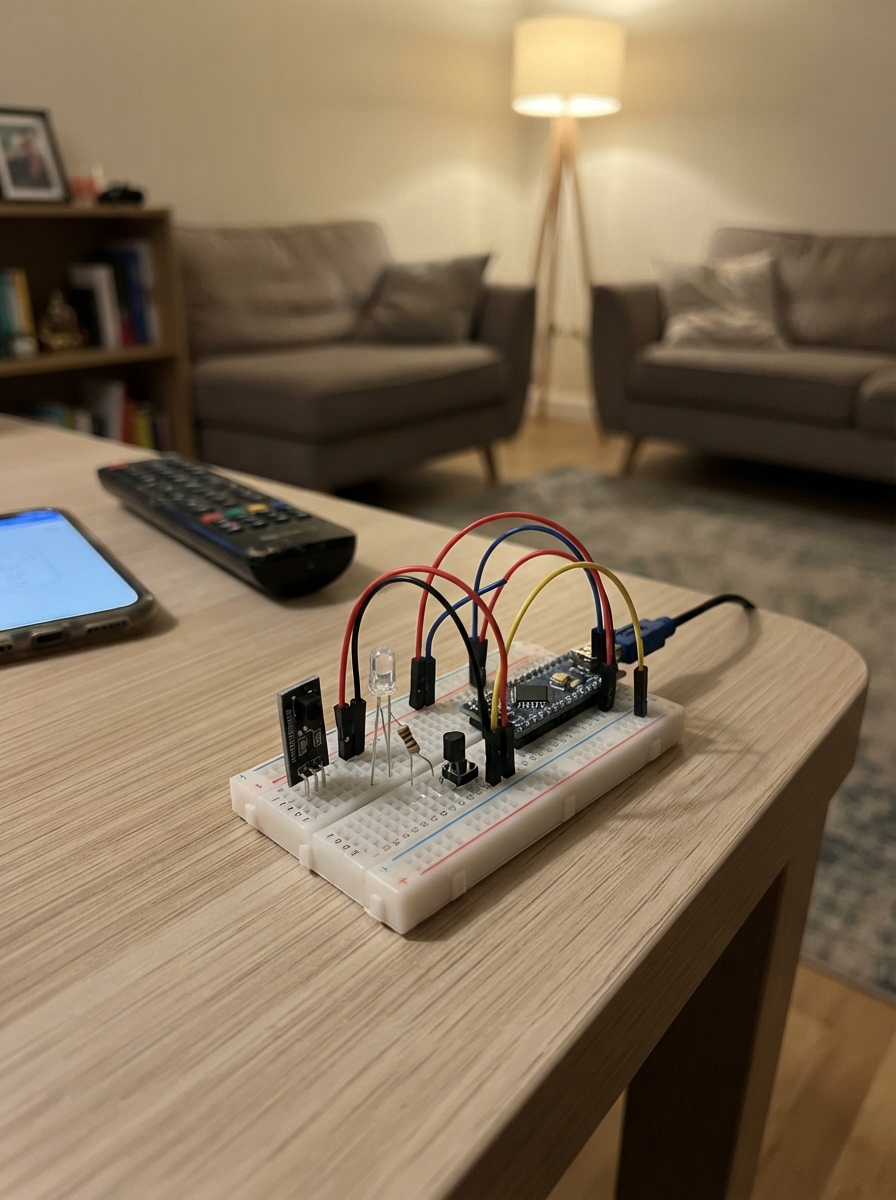
This universal device remote lets you control any infrared-equipped device by learning and replaying its commands. Built around an ESP32 microcontroller, it uses an IR receiver to capture remote signals and an infrared LED driver to transmit them back, all controlled through four programmable buttons for power, volume up, volume down, and mute.
The guide provides a complete wiring diagram, parts list, and step-by-step assembly instructions for connecting the IR receiver, LED driver circuit, and push buttons to the ESP32. The included firmware handles command learning, storage in EEPROM, and transmission, so after assembly you simply hold each button to teach it a command from your original remote.
Wiring diagram

Gather all the parts
Assemble it in 5 steps
1. Place the NodeMCU and the four buttons
Put the NodeMCU across the center gap of the breadboard. Place four push buttons so each button straddles the breadboard center gap. Label them Power, Up, Down, and Mute so they do not get mixed up.
- A button has two pairs of internally connected legs; use one leg from each opposite side of the button.
- Do not connect any button to the NodeMCU 3V3 pin; these buttons connect their signal pin to GND only when pressed.
2. Wire the four buttons
Join one side of every button to a NodeMCU GND pin: Power button GND → GND (ground), Up button GND → GND (ground), Down button GND → GND (ground), Mute button GND → GND (ground). Connect the opposite sides: Power button SIGNAL → D6 / GPIO12 (signal), Up button SIGNAL → D7 / GPIO13 (signal), Down button SIGNAL → D0 / GPIO16 (signal), Mute button SIGNAL → RX / GPIO3 (signal).
- The program supplies the small internal pull-up connection, so no extra resistors are needed for the buttons.
- A quick tap sends a saved command; holding any button for about two seconds starts learning for that button.
- Keep the Mute button wire away from the NodeMCU RST pin; RST would restart the board instead of reading a button press.
3. Wire the infrared receiver
With the TSOP38238's pin labels facing you, connect VS → 3V3 (power), GND → GND (ground), and OUT → D1 / GPIO5 (data). This part faces the original remote while learning its commands.
- Check the printed pin labels on your receiver module or its datasheet; loose bare TSOP38238 parts do not always have the same left-to-right leg order as breakout boards.
- Make sure VS and GND are not swapped — swapped power can damage the infrared receiver.
4. Build the infrared LED driver
Connect NodeMCU D2 / GPIO4 → one end of the 1 kΩ base resistor (signal), and the other end of that resistor → the BASE leg of the 2N2222A transistor (signal). Connect the transistor EMITTER → GND (ground). Connect the transistor COLLECTOR → the short leg of the 940 nm infrared LED (signal). Connect the infrared LED long leg → one end of the 100 Ω resistor (signal), then the other end of that resistor → 3V3 (power). Point the LED toward the appliance you want to control.
- The long LED leg is normally the positive leg. On a flat-edged LED body, the flat side marks the short negative leg.
- Check the exact 2N2222A or BC547 package pinout before inserting it: transistor leg order differs between part variants.
- Do not connect the infrared LED straight to a NodeMCU pin — the transistor and both resistors prevent damage to the board and LED.
- Do not swap the infrared LED legs; it will not send light when reversed.
5. Power up and teach the four commands
Plug the NodeMCU into your computer with USB. Hold one of your new buttons for about two seconds, then aim the original remote at the TSOP38238 receiver and press the matching original button within 12 seconds. Teach Power with the original power key, Up with its up key, Down with its down key, and Mute with its mute key. A short press on your new button then sends its saved command through the infrared LED.
- Keep the original remote about 2 to 10 cm from the receiver while teaching.
- A phone camera can often show the infrared LED as a faint blinking purple-white light while sending.
- Do not look closely into the infrared LED while testing; its light is invisible but can still be intense at close range.
Review all connections
1. Connections between "ir_receiver" and "ESP32"
2. Connections between "ir_led_resistor" and "ESP32"
3. Connections between "ir_driver" and "ESP32"
4. Connections between "base_resistor" and "ESP32"
5. Connections between "button_power" and "ESP32"
6. Connections between "button_up" and "ESP32"
7. Connections between "button_down" and "ESP32"
8. Connections between "button_mute" and "ESP32"
Deploy the firmware
#include <Arduino.h>
#include <EEPROM.h>
#include <IRrecv.h>
#include <IRsend.h>
#include <IRutils.h>


// Hoisted type definitions
struct CommandSlot {
  uint16_t marker;
  uint16_t length;
  uint16_t raw[MAX_RAW_TICKS];
};


// Forward declarations
uint16_t slotAddress(uint8_t index);
void loadSlots();
void saveSlot(uint8_t index);
void flashBuiltIn(uint8_t count);
bool waitForIrCommand(uint8_t slotIndex);
void sendCommand(uint8_t slotIndex);
void handleButtons();

constexpr uint8_t IR_RX_PIN = 5;       // D1
constexpr uint8_t IR_TX_PIN = 4;       // D2, through 1 kOhm resistor and transistor
constexpr uint8_t POWER_BUTTON_PIN = 12; // D6
constexpr uint8_t UP_BUTTON_PIN = 13;    // D7
constexpr uint8_t DOWN_BUTTON_PIN = 16;  // D0
constexpr uint8_t MUTE_BUTTON_PIN = 3;   // RX

constexpr uint16_t EEPROM_BYTES = 2048;
constexpr uint16_t SLOT_BYTES = 500;
constexpr uint8_t BUTTON_COUNT = 4;
constexpr uint16_t MAX_RAW_TICKS = 240;
constexpr uint16_t LEARN_HOLD_MS = 1800;
constexpr uint16_t DEBOUNCE_MS = 35;


constexpr uint16_t SLOT_MARKER = 0x5249;
const uint8_t buttonPins[BUTTON_COUNT] = {
  POWER_BUTTON_PIN, UP_BUTTON_PIN, DOWN_BUTTON_PIN, MUTE_BUTTON_PIN
};
const char *buttonNames[BUTTON_COUNT] = {"POWER", "UP", "DOWN", "MUTE"};

IRrecv irReceiver(IR_RX_PIN, 1024, 15, true);
IRsend irSender(IR_TX_PIN);
decode_results received;
CommandSlot slots[BUTTON_COUNT];
bool buttonWasDown[BUTTON_COUNT] = {false, false, false, false};
uint32_t pressStartedAt[BUTTON_COUNT] = {0, 0, 0, 0};
uint32_t lastActionAt = 0;

uint16_t slotAddress(uint8_t index) {
  return index * SLOT_BYTES;
}

void loadSlots() {
  for (uint8_t i = 0; i < BUTTON_COUNT; i++) {
    EEPROM.get(slotAddress(i), slots[i]);
    if (slots[i].marker != SLOT_MARKER || slots[i].length == 0 || slots[i].length > MAX_RAW_TICKS) {
      slots[i].marker = 0;
      slots[i].length = 0;
    }
  }
}

void saveSlot(uint8_t index) {
  EEPROM.put(slotAddress(index), slots[index]);
  EEPROM.commit();
}

void flashBuiltIn(uint8_t count) {
  for (uint8_t i = 0; i < count; i++) {
    digitalWrite(LED_BUILTIN, LOW);
    delay(100);
    digitalWrite(LED_BUILTIN, HIGH);
    delay(120);
  }
}

bool waitForIrCommand(uint8_t slotIndex) {
  Serial.printf("Point the original remote at the receiver and press its %s button.\n", buttonNames[slotIndex]);
  const uint32_t deadline = millis() + 12000;
  while (millis() < deadline) {
    if (irReceiver.decode(&received)) {
      const uint16_t copyLength = min<uint16_t>(received.rawlen, MAX_RAW_TICKS);
      if (copyLength > 1) {
        slots[slotIndex].marker = SLOT_MARKER;
        slots[slotIndex].length = copyLength;
        for (uint16_t i = 0; i < copyLength; i++) {
          slots[slotIndex].raw[i] = received.rawbuf[i];
        }
        saveSlot(slotIndex);
        Serial.printf("Saved %s command (%u timing marks).\n", buttonNames[slotIndex], copyLength);
        irReceiver.resume();
        flashBuiltIn(3);
        return true;
      }
      irReceiver.resume();
    }
    delay(1);
  }
  Serial.println("No infrared command received; learning cancelled.");
  flashBuiltIn(1);
  return false;
}

void sendCommand(uint8_t slotIndex) {
  if (slots[slotIndex].marker != SLOT_MARKER || slots[slotIndex].length == 0) {
    Serial.printf("%s has not been learned yet. Hold its button for two seconds to learn it.\n", buttonNames[slotIndex]);
    flashBuiltIn(1);
    return;
  }

  irReceiver.disableIRIn();
  irSender.sendRaw(slots[slotIndex].raw, slots[slotIndex].length, 38);
  irReceiver.enableIRIn();
  Serial.printf("Sent %s.\n", buttonNames[slotIndex]);
  flashBuiltIn(2);
}

void handleButtons() {
  const uint32_t now = millis();
  for (uint8_t i = 0; i < BUTTON_COUNT; i++) {
    const bool down = digitalRead(buttonPins[i]) == LOW;
    if (down && !buttonWasDown[i]) {
      buttonWasDown[i] = true;
      pressStartedAt[i] = now;
    }

    if (!down && buttonWasDown[i]) {
      const uint32_t heldFor = now - pressStartedAt[i];
      buttonWasDown[i] = false;
      if (now - lastActionAt < DEBOUNCE_MS) {
        continue;
      }
      lastActionAt = now;
      if (heldFor >= LEARN_HOLD_MS) {
        waitForIrCommand(i);
      } else {
        sendCommand(i);
      }
    }
  }
}

void setup() {
  Serial.begin(115200);
  EEPROM.begin(EEPROM_BYTES);
  pinMode(LED_BUILTIN, OUTPUT);
  digitalWrite(LED_BUILTIN, HIGH);

  for (uint8_t i = 0; i < BUTTON_COUNT; i++) {
    pinMode(buttonPins[i], INPUT_PULLUP);
  }

  loadSlots();
  irSender.begin();
  irReceiver.enableIRIn();
  Serial.println("Learning IR remote ready. Tap a button to send. Hold it for two seconds, then press the matching key on your original remote to learn.");
  flashBuiltIn(2);
}

void loop() {
  handleButtons();
}
Remix this project
Make it yours in one click
Open a full copy of this project in your own Schematik workspace — diagram, code, parts, and assembly steps included. Swap the sensor, add features, or redesign the whole thing with AI. The author's original stays untouched.