Community project
UV Alert Wristband Logger
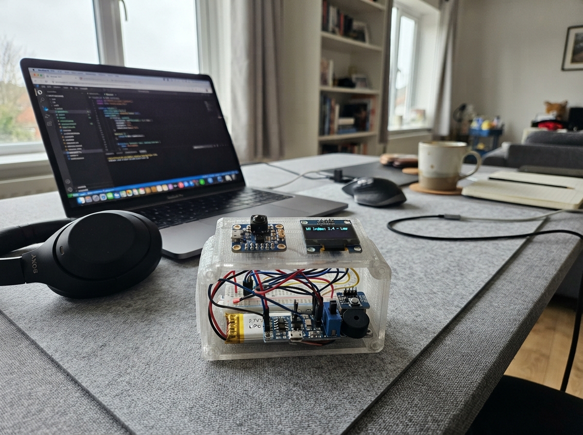
This wristband logger continuously monitors ultraviolet radiation and logs exposure data to a microSD card, alerting the wearer when UV intensity reaches unsafe levels. Built around an ESP32 microcontroller, the device pairs an LTR390 UV sensor with a real-time clock, OLED display, and onboard data storage to create a portable UV tracking system that runs for hours on a small LiPo battery.
The guide provides a complete wiring diagram, full parts list with sourcing notes, and step-by-step assembly instructions for soldering the sensor breakouts, display, microSD reader, and alert components onto perfboard. Included firmware handles sensor calibration, SD logging, real-time display updates, and multi-level UV alerts via buzzer and NeoPixel indicator, with all configuration parameters exposed for customization.
Wiring diagram
Gather all the parts
Assemble it in 10 steps
1. Lay out the parts before soldering
Place the ESP32-C3 Super Mini and the small boards on the perfboard so the OLED faces outward and the LTR390 sensor can see daylight. Keep the battery pouch away from sharp perfboard edges, the motor away from the sensor, and the microSD socket accessible. Use red wire for positive power, black for ground, and other colors for signal wires.
- Dry-fit parts and check the wristband still closes before soldering.
- Do not bend, puncture, crush, or solder directly to the LiPo pouch; a damaged lithium battery can catch fire.
2. Wire the sensor, screen, and clock together
With the battery disconnected, connect the LTR390, OLED, and DS3231 to the same two signal wires: each SDA pin to GPIO0 (data), and each SCL pin to GPIO1 (clock). Connect LTR390 VIN, OLED VCC, and RTC VIN to the 3V3 rail (power); connect their GND pins to GND (ground).
- The three devices share the two I2C wires; this is intentional because they use different addresses.
- Keep these three modules on 3V3, not 5V; 5V on their signal pull-ups can damage the ESP32-C3.
3. Connect the microSD reader
Connect the card reader 3V pin to 3V3 (power), GND to GND (ground), CLK to GPIO4 (clock), MISO to GPIO5 (card-to-board data), MOSI to GPIO6 (board-to-card data), and CS to GPIO7 (card select). Slide the FAT32 microSD card into its socket until it clicks.
- Keep these signal wires short; long loose wires can make the card unreliable.
- This reader is 3.3 V only; do not connect its power or signal pins to 5V.
4. Install the 5 V data buffer and color indicator
Place the 74AHCT125N DIP-14 chip with its notch facing up. Connect chip pin 14 to 5V (chip power), pin 7 to GND (ground), pin 1 (/1OE) to GND (enable), pin 2 (1A) to GPIO10 (input data), and pin 3 (1Y) to one end of the pixel_data_resistor (buffered output). Connect the resistor’s other end to color_indicator DIN (color data). Connect color_indicator VCC to 5V (power) and GND to GND (ground). Tie unused inputs at pins 6, 9, and 12 to GND (quiet inputs); tie unused active-low enables at pins 4, 10, and 13 to 5V (disabled outputs). Leave the unused outputs at pins 5, 8, and 11 unconnected. Put logic_bypass_cap across chip pins 14 and 7 (supply smoothing), and connect pixel_bulk_cap positive to 5V and its striped negative lead to GND (LED supply smoothing).
- Place the 100 nF capacitor close to chip pins 14 and 7. The 330 Ω resistor goes in series between chip pin 3 and the color indicator DIN pin.
- Make sure the 74AHCT125N notch faces the correct way before soldering; reversed chip power can damage it. The 1000 µF capacitor’s striped side is negative and must go to GND.
5. Wire the vibration motor through its transistor
Connect vibration_motor M+ to 3V3 (motor power) and M- to motor_driver COLLECTOR (switched motor return). Connect motor_driver EMITTER to GND (ground). Connect GPIO20 to one end of motor_base_resistor and its other end to motor_driver BASE (limited control signal). Connect motor_flyback_diode CATHODE—the banded end—to vibration_motor M+ (motor positive), and ANODE to motor_driver COLLECTOR (motor return).
- The motor should pulse together with the buzzer when the UV alert starts.
- Never power the motor directly from GPIO20; the transistor carries the motor current. The diode band must face the motor’s positive lead or the circuit may short when switched on.
6. Connect the sounder
Connect buzzer_alert SIG to GPIO3 (tone signal) and its GND pin to GND (ground).
- The passive piezo leads are not polarized; either lead may go to SIG or GND.
- Do not connect the piezo signal pin to 5V; its drive signal comes from GPIO3.
7. Put the backup cell in the clock
Place the CR1220 in the RTC holder with its positive face matching the holder’s + mark. If your RTC board has separate BAT pads instead, connect the coin cell positive to BAT and negative to GND.
- The coin cell keeps the RTC time while the wristband’s main switch is off.
- Reversed coin-cell polarity can stop the clock or damage the RTC module.
8. Set up the charger for the small battery
Confirm the TP4056 board is the protected version. Replace its original RPROG resistor with charger_rprog (the 10 kΩ resistor) so the charge current is about 120 mA. Connect battery positive to TP4056 B+ (battery positive) and battery negative to B- (battery negative). Connect charger IN+ to a separate 5V charging input (charge positive) and IN- to GND (charge return).
- The resistor replaces the tiny RPROG part on the charger board; it is not an extra resistor wired across the battery.
- Do not charge this 350 mAh cell with the TP4056’s common 1 A setting; it can overheat or damage the battery. Stop using a swollen, hot, or punctured cell.
9. Connect the switch and set the converter output
Connect TP4056 OUT+ to switch_power COM (switched positive in), switch_power A to boost_5v VIN+ (battery power), and TP4056 OUT- to boost_5v VIN- (ground return); leave switch_power B unused. Before connecting the board, power the TPS63020 module and use a multimeter to set its output to exactly 5.0 V. Then connect boost_5v VOUT+ to the board 5V/VIN input and color_indicator VCC (regulated 5V), and connect VOUT- to common GND (return). Connect level_shifter VCC to 5V (chip power).
- The TPS63020 module’s output selector or solder jumper must be set to 5V; its usual default may be 3.3V.
- Do not connect the converter to the board until a meter reads 5.0 V. Do not power the board from USB while the battery converter is also connected; competing power sources can damage hardware.
10. Check the wires and secure the wristband
With the LiPo still disconnected, inspect both sides of the perfboard for solder bridges. Confirm every module ground joins GND, the sensor/display/RTC/microSD power pins are on 3V3, and only the color indicator and 74AHCT125 use the 5V rail. Make sure the motor turns on only through the transistor. Insulate exposed battery wires and secure the perfboard and battery in the wristband so nothing sharp presses into the LiPo.
- For a first test, leave the LiPo disconnected and use the board’s USB connection; connect battery power only after the 5V output and wiring have been checked.
- Do not wear the band while soldering or while checking for shorts, and do not charge it while wearing it.
Review all connections
1. Connections between "ltr390_uv" and "ESP32"
2. Connections between "oled_096" and "ESP32"
3. Connections between "battery_350" and "ESP32"
4. Connections between "charger_tp4056" and "ESP32"
5. Connections between "switch_power" and "ESP32"
6. Connections between "boost_5v" and "ESP32"
7. Connections between "buzzer_alert" and "ESP32"
8. Connections between "rtc_ds3231" and "ESP32"
9. Connections between "rtc_coin_cell" and "ESP32"
10. Connections between "sd_module" and "ESP32"
11. Connections between "sd_card" and "ESP32"
12. Connections between "level_shifter" and "ESP32"
13. Connections between "pixel_bulk_cap" and "ESP32"
14. Connections between "logic_bypass_cap" and "ESP32"
15. Connections between "motor_base_resistor" and "ESP32"
16. Connections between "motor_driver" and "ESP32"
17. Connections between "vibration_motor" and "ESP32"
18. Connections between "pixel_data_resistor" and "ESP32"
19. Connections between "motor_flyback_diode" and "ESP32"
20. Connections between "color_indicator" and "ESP32"
Deploy the firmware
#include <Arduino.h>
#include <Wire.h>
#include <SPI.h>
#include <SD.h>
#include <math.h>
#include <Adafruit_LTR390.h>
#include <Adafruit_GFX.h>
#include <Adafruit_SSD1306.h>
#include <Adafruit_NeoPixel.h>
#include <RTClib.h>

// ESP32-C3 SuperMini wiring
constexpr uint8_t I2C_SDA_PIN = 0;
constexpr uint8_t I2C_SCL_PIN = 1;
constexpr uint8_t BUZZER_PIN = 3;
constexpr uint8_t SD_SCK_PIN = 4;
constexpr uint8_t SD_MISO_PIN = 5;
constexpr uint8_t SD_MOSI_PIN = 6;
constexpr uint8_t SD_CS_PIN = 7;
constexpr uint8_t NEOPIXEL_PIN = 10;
constexpr uint8_t MOTOR_PIN = 20;

constexpr int SCREEN_WIDTH = 128;
constexpr int SCREEN_HEIGHT = 64;
constexpr uint8_t OLED_ADDRESS = 0x3C;
constexpr float UV_ALERT_UVI = 3.0f;
constexpr float UV_HIGH_UVI = 6.0f;
constexpr uint32_t LOG_INTERVAL_MS = 60000UL;

Adafruit_LTR390 ltr;
Adafruit_SSD1306 display(SCREEN_WIDTH, SCREEN_HEIGHT, &Wire, -1);
Adafruit_NeoPixel pixel(1, NEOPIXEL_PIN, NEO_GRB + NEO_KHZ800);
RTC_DS3231 rtc;

bool sensorOk = false;
bool displayOk = false;
bool rtcOk = false;
bool sdOk = false;
bool haveUv = false;
bool haveAls = false;

enum SensorMode : uint8_t { MODE_UV, MODE_ALS };
SensorMode sensorMode = MODE_UV;
uint32_t sensorModeStarted = 0;
uint32_t uvRaw = 0;
uint32_t alsRaw = 0;
float uvIndexEstimate = 0.0f;
float luxEstimate = 0.0f;

int lastRenderedUviTenths = -999;
int lastRenderedLux = -999;
int lastRenderedCategory = -1;
int lastRenderedMinute = -1;
int lastLedCategory = -1;
uint32_t lastDisplayCheck = 0;
uint32_t lastLogAt = 0;
uint32_t lastAlertAt = 0;

bool buzzerPatternActive = false;
bool buzzerOn = false;
uint8_t beepCount = 0;
uint8_t beepTarget = 0;
uint32_t buzzerTransitionAt = 0;

int uvCategory(float value) {
  if (value < UV_ALERT_UVI) return 0;
  if (value < UV_HIGH_UVI) return 1;
  return 2;
}

void updatePixel() {
  if (!sensorOk || !haveUv) return;
  const int category = uvCategory(uvIndexEstimate);
  if (category == lastLedCategory) return;

  if (category == 0) {
    pixel.setPixelColor(0, pixel.Color(0, 0, 36));
  } else if (category == 1) {
    pixel.setPixelColor(0, pixel.Color(36, 22, 0));
  } else {
    pixel.setPixelColor(0, pixel.Color(40, 0, 0));
  }
  pixel.show();
  lastLedCategory = category;
}

void renderDashboard() {
  if (!displayOk) return;

  const int category = haveUv ? uvCategory(uvIndexEstimate) : 0;
  const int uviTenths = haveUv ? static_cast<int>(lroundf(uvIndexEstimate * 10.0f)) : -1;
  const int luxShown = haveAls ? static_cast<int>(lroundf(luxEstimate)) : -1;
  int currentMinute = -1;
  DateTime clockNow(2000, 1, 1, 0, 0, 0);
  if (rtcOk) {
    clockNow = rtc.now();
    currentMinute = clockNow.hour() * 60 + clockNow.minute();
  }

  if (uviTenths == lastRenderedUviTenths && luxShown == lastRenderedLux &&
      category == lastRenderedCategory && currentMinute == lastRenderedMinute) {
    return;
  }
  lastRenderedUviTenths = uviTenths;
  lastRenderedLux = luxShown;
  lastRenderedCategory = category;
  lastRenderedMinute = currentMinute;

  display.clearDisplay();
  display.setTextSize(1);
  display.setTextColor(SSD1306_WHITE);
  display.setCursor(0, 0);
  display.println("UV ALERT WRISTBAND");
  display.setCursor(0, 14);
  display.print("UVI~ ");
  if (haveUv) display.print(uvIndexEstimate, 1);
  else display.print("--");
  display.setCursor(68, 14);
  display.print("Lux~ ");
  if (haveAls) display.print(luxShown);
  else display.print("--");
  display.setCursor(0, 30);
  if (!sensorOk) {
    display.print("UV sensor not found");
  } else if (category == 0) {
    display.print("UV: LOW");
  } else if (category == 1) {
    display.print("UV: MODERATE - cover up");
  } else {
    display.print("UV: HIGH - protect skin");
  }
  display.setCursor(0, 48);
  if (rtcOk) {
    display.print("Time ");
    if (clockNow.hour() < 10) display.print('0');
    display.print(clockNow.hour());
    display.print(':');
    if (clockNow.minute() < 10) display.print('0');
    display.print(clockNow.minute());
  } else {
    display.print("RTC unavailable");
  }
  display.setCursor(0, 58);
  display.print(sdOk ? "Log: SD ready" : "Log: SD unavailable");
  display.display();
}

void stopBuzzer() {
  if (buzzerOn) noTone(BUZZER_PIN);
  digitalWrite(MOTOR_PIN, LOW);
  buzzerOn = false;
  buzzerPatternActive = false;
}

void serviceBuzzer(uint32_t now) {
  if (!sensorOk || !haveUv || uvIndexEstimate < UV_ALERT_UVI) {
    stopBuzzer();
    return;
  }

  const int category = uvCategory(uvIndexEstimate);
  const uint32_t repeatMs = (category >= 2) ? 15000UL : 30000UL;
  if (!buzzerPatternActive && static_cast<uint32_t>(now - lastAlertAt) >= repeatMs) {
    lastAlertAt = now;
    buzzerPatternActive = true;
    buzzerOn = true;
    beepCount = 1;
    beepTarget = (category >= 2) ? 3 : 2;
    tone(BUZZER_PIN, 4000);
    digitalWrite(MOTOR_PIN, HIGH);
    buzzerTransitionAt = now + ((category >= 2) ? 240UL : 150UL);
  }

  if (!buzzerPatternActive || static_cast<int32_t>(now - buzzerTransitionAt) < 0) return;

  if (buzzerOn) {
    noTone(BUZZER_PIN);
    digitalWrite(MOTOR_PIN, LOW);
    buzzerOn = false;
    if (beepCount >= beepTarget) {
      buzzerPatternActive = false;
    } else {
      buzzerTransitionAt = now + 120UL;
    }
  } else {
    tone(BUZZER_PIN, 4000);
    digitalWrite(MOTOR_PIN, HIGH);
    buzzerOn = true;
    ++beepCount;
    buzzerTransitionAt = now + ((category >= 2) ? 240UL : 150UL);
  }
}

void serviceSensor(uint32_t now) {
  if (!sensorOk || static_cast<uint32_t>(now - sensorModeStarted) < 420UL) return;
  if (!ltr.newDataAvailable()) return;

  if (sensorMode == MODE_UV) {
    uvRaw = ltr.readUVS();
    // At 18x gain and 20-bit resolution, the LTR390 reference is about 2300 counts/UVI.
    // This is an estimate, not a calibrated medical or regulatory UV instrument.
    uvIndexEstimate = static_cast<float>(uvRaw) / 2300.0f;
    haveUv = true;
    ltr.setMode(LTR390_MODE_ALS);
    sensorMode = MODE_ALS;
  } else {
    alsRaw = ltr.readALS();
    // Approximate lux at 18x gain and 400 ms integration (20-bit resolution).
    luxEstimate = static_cast<float>(alsRaw) / 120.0f;
    haveAls = true;
    ltr.setMode(LTR390_MODE_UVS);
    sensorMode = MODE_UV;
  }
  sensorModeStarted = now;
  updatePixel();
}

void initializeCard() {
  SPI.begin(SD_SCK_PIN, SD_MISO_PIN, SD_MOSI_PIN, SD_CS_PIN);
  sdOk = SD.begin(SD_CS_PIN, SPI, 4000000);
  if (!sdOk) {
    Serial.println("microSD not ready; readings will not be logged.");
    return;
  }

  if (!SD.exists("/uv_alert.csv")) {
    File file = SD.open("/uv_alert.csv", FILE_WRITE);
    if (file) {
      file.println("timestamp,uv_raw,uvi_estimate,lux_estimate,alert_level");
      file.close();
    }
  }
}

void appendLog() {
  if (!sdOk || !haveUv || !haveAls) return;

  char timestamp[24];
  if (rtcOk) {
    const DateTime now = rtc.now();
    snprintf(timestamp, sizeof(timestamp), "%04d-%02d-%02d %02d:%02d:%02d",
             now.year(), now.month(), now.day(), now.hour(), now.minute(), now.second());
  } else {
    snprintf(timestamp, sizeof(timestamp), "NO_RTC");
  }

  const char *level = (uvCategory(uvIndexEstimate) == 0) ? "LOW" :
                      (uvCategory(uvIndexEstimate) == 1) ? "MODERATE" : "HIGH";
  char row[112];
  snprintf(row, sizeof(row), "%s,%lu,%.2f,%.1f,%s",
           timestamp, static_cast<unsigned long>(uvRaw), uvIndexEstimate, luxEstimate, level);
  File file = SD.open("/uv_alert.csv", FILE_APPEND);
  if (file) {
    file.println(row);
    file.close();
  } else {
    sdOk = false;
  }
}

void setup() {
  Serial.begin(115200);
  delay(150);

  pinMode(MOTOR_PIN, OUTPUT);
  digitalWrite(MOTOR_PIN, LOW);

  Wire.begin(I2C_SDA_PIN, I2C_SCL_PIN);

  pixel.begin();
  pixel.setBrightness(24);
  pixel.clear();
  pixel.show();

  displayOk = display.begin(SSD1306_SWITCHCAPVCC, OLED_ADDRESS);

  sensorOk = ltr.begin();
  if (sensorOk) {
    ltr.setGain(LTR390_GAIN_18);
    ltr.setResolution(LTR390_RESOLUTION_20BIT);
    ltr.setMode(LTR390_MODE_UVS);
    sensorMode = MODE_UV;
    sensorModeStarted = millis();
  } else {
    Serial.println("LTR390 not found.");
  }

  rtcOk = rtc.begin();
  if (rtcOk && rtc.lostPower()) {
    // Sets a reasonable starting time; insert the CR1220 so the clock keeps running when off.
    rtc.adjust(DateTime(F(__DATE__), F(__TIME__)));
  }
  if (!rtcOk) Serial.println("DS3231 not found.");

  initializeCard();
  lastLogAt = millis() - LOG_INTERVAL_MS;
  lastAlertAt = millis() - 30000UL;
  renderDashboard();
}

void loop() {
  const uint32_t now = millis();
  serviceSensor(now);
  serviceBuzzer(now);

  if (static_cast<uint32_t>(now - lastDisplayCheck) >= 500UL) {
    lastDisplayCheck = now;
    renderDashboard();
  }

  if (static_cast<uint32_t>(now - lastLogAt) >= LOG_INTERVAL_MS) {
    lastLogAt = now;
    appendLog();
  }

  delay(20);
}
Remix this project
Make it yours in one click
Open a full copy of this project in your own Schematik workspace, diagram, code, parts, and assembly steps included. Swap the sensor, add features, or redesign the whole thing with AI. The author's original stays untouched.